PBR - Using Terrain Shader
The Terrain Shader, extends on the Standard Shader and allows the blending between multiple albedo roughness maps. There are some functionality switches to help support older blending techniques that were used before PBR, as well as a new splatter map mode and there are also some additional features to help us get better lighting on terrain.
You can find the technical reference for this shader here: IBL Terrain Shader and IBL Terrain Legacy Shader.
I recommend that you read PBR - Using Standard Shader before proceeding with this article, as I do not cover items again which are covered there such as UV options and Material Adjust settings.
Key Concepts
There are a couple of concepts that need explaining before we go too far. These run through out the shader regardless of settings. These are a mixture of maps used, parameters available and shader configuration options.
Mix Maps
Regardless of which blending mode is used, it's worth noting that all blending uses Mixmap Calculations.
You can find some background information on this here:
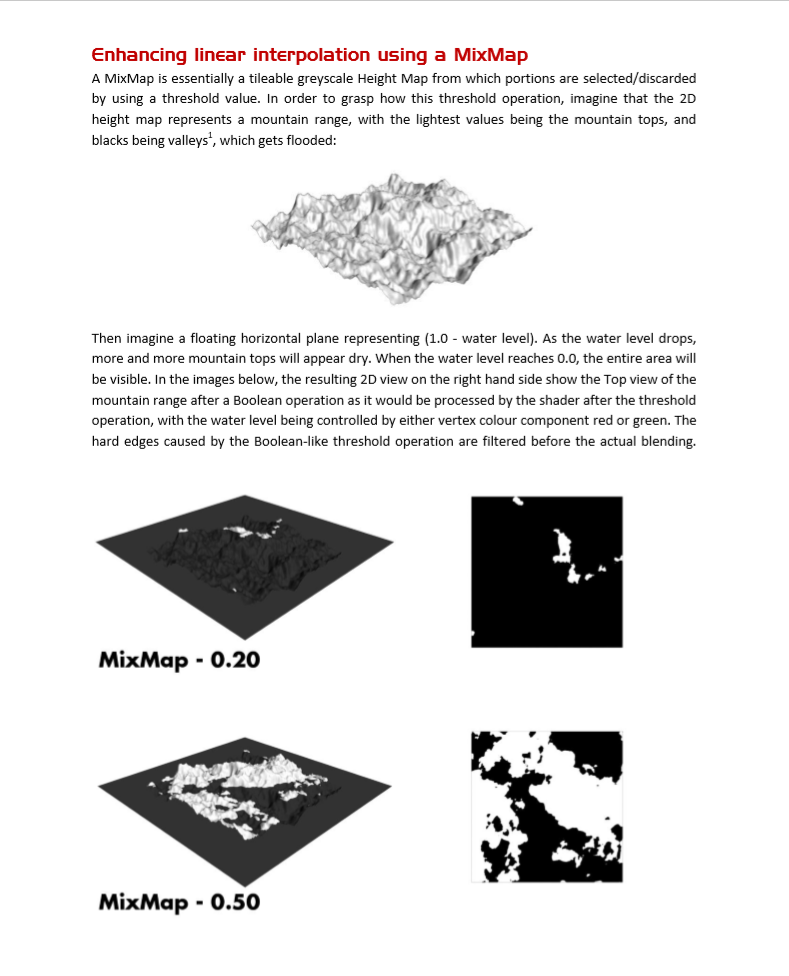
Mix map blending makes use of:
- Input Value: Shows how much we want this map to be used
- Mix Map: A noise map used to break up the blending
- Bias: A static value which controls how suddenly the blending occurs.
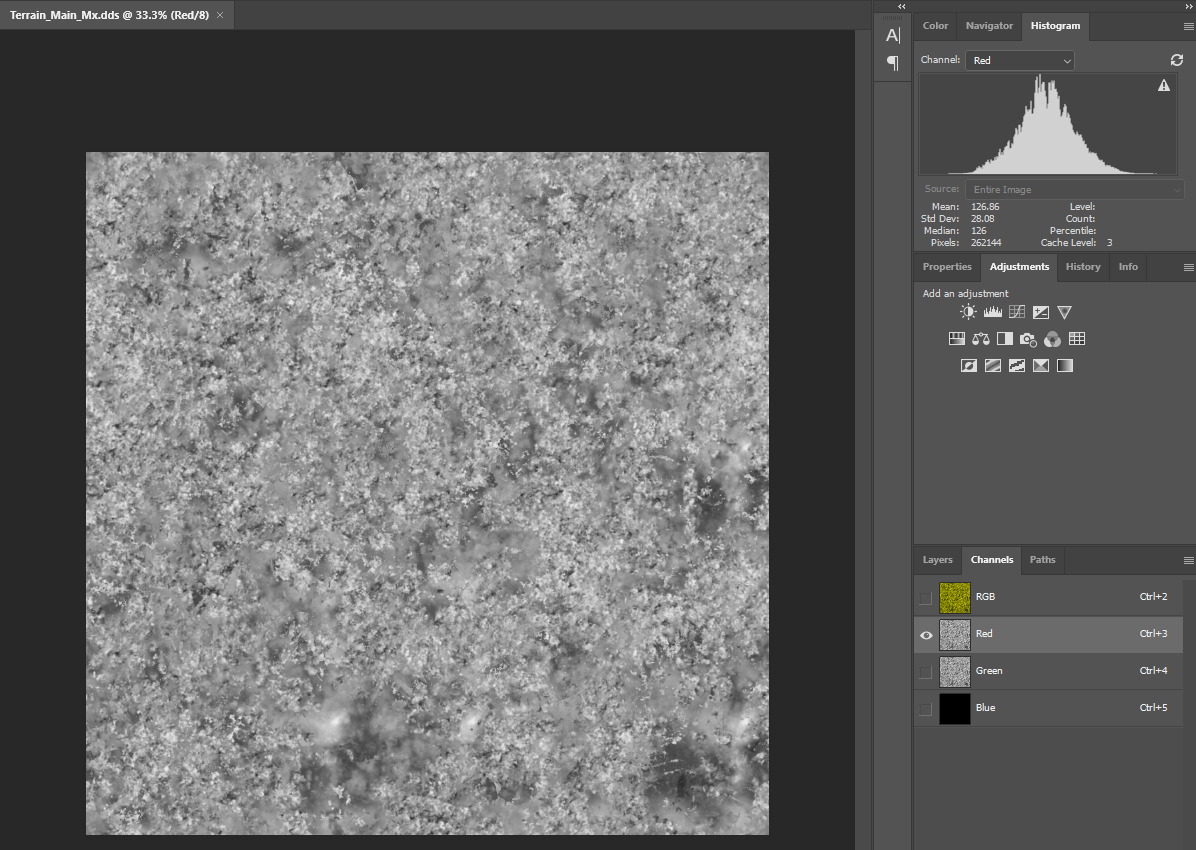
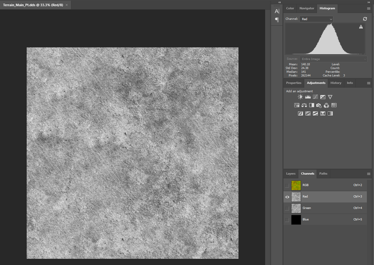
A sample Mix Map can be seen beneath, note it should be centred around 0.5. The terrain shader takes the MixMap input from the red channel. The green channel is used as a specular mask.
This blend percentage is calculated as follows, and then used in a linear interpolate.
- BlendPercentage = saturate((MixMap - Input) / bias)
The outputs of these calculations vary depending on the Mix Map value at any given point. However assuming that the value is an average of 0.5 and a typical bias of 0.25, then we can expect the following inputs to result in the following outputs when blending from AlbedoA to AlbedoB:
- Input lower than 80 will typically not add any details, leaving completely AlbedoA.
- A range of 90-128 can be used to blend in very subtle details from AlbedoB, for example adding some very fine dirt details at the side of the road.
- A range of 128-160 will mostly result in AlbedoB being blended in, however some details from AlbedoA will still occur.
- Input over 175 will typically just result in AlbedoB being completely blended in.
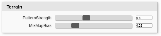
The bias of the blending can be configured in the Terrain parameters section of the shader.

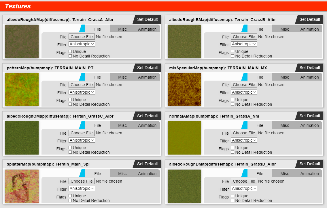
Albedo Maps
You can configure in the shader configuration depending on the blending mode upto 3 or upto 4 albedo maps. Each albedo map packs the roughness map into the alpha channel.
Typically these albedo maps are setup as square standard tiling maps, quite heavily tiled, with different variations allowing the blending to add the extra details in the medium and far distance. For example:
- AlbedoA: Dry Dirt / Soil / Sparse Grass
- AlbedoB: Undersaturated / Dry Grass
- AlbedoC: Oversaturated / Very Green Grass
- AlbedoD: Normally saturated Grass
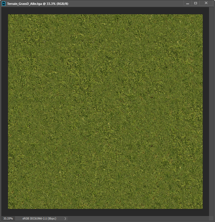
However this does not have to be the case, maps can be authored as desired, and in a variety of ways.
Normal Maps
All modes allow you to choose to use either 1 or 2 normal maps.
When you have two maps enabled, a Normal Blends section will appear under parameters. This allows you to configure the blend of these two normal maps which is used when each Albedo Map is the final output.
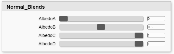
There is also a Normal Intensity section where you can adjust on a per albedo map basis how strong the normal effect is.
Pattern Maps
In the past a simple multiplication map was used to break up the blending of the diffuse maps. This concept has been extended for all blending modes on the PBR shader, and now we make use of a Pattern Map instead.
This is two channels of grey scale data which is centred around 0.5. The input uses an overlay function to be applied ontop of the terrain albedo blending, allowing now to lighten as well as darken the output.
Different blending modes allow different blending between pattern maps, and are explained in the Blending Mode sections later.
The example beneath was generated from satellite imagery of some large open field areas.
The Pattern Map should make full use of the complete channel spectrum, and then use the Pattern Strength parameter to scale down the effect to increase fidelity and reduce texture artefacts.
However be careful to keep the effects relatively subtle or you can introduce colour distortion to your maps.
UVW Mapping
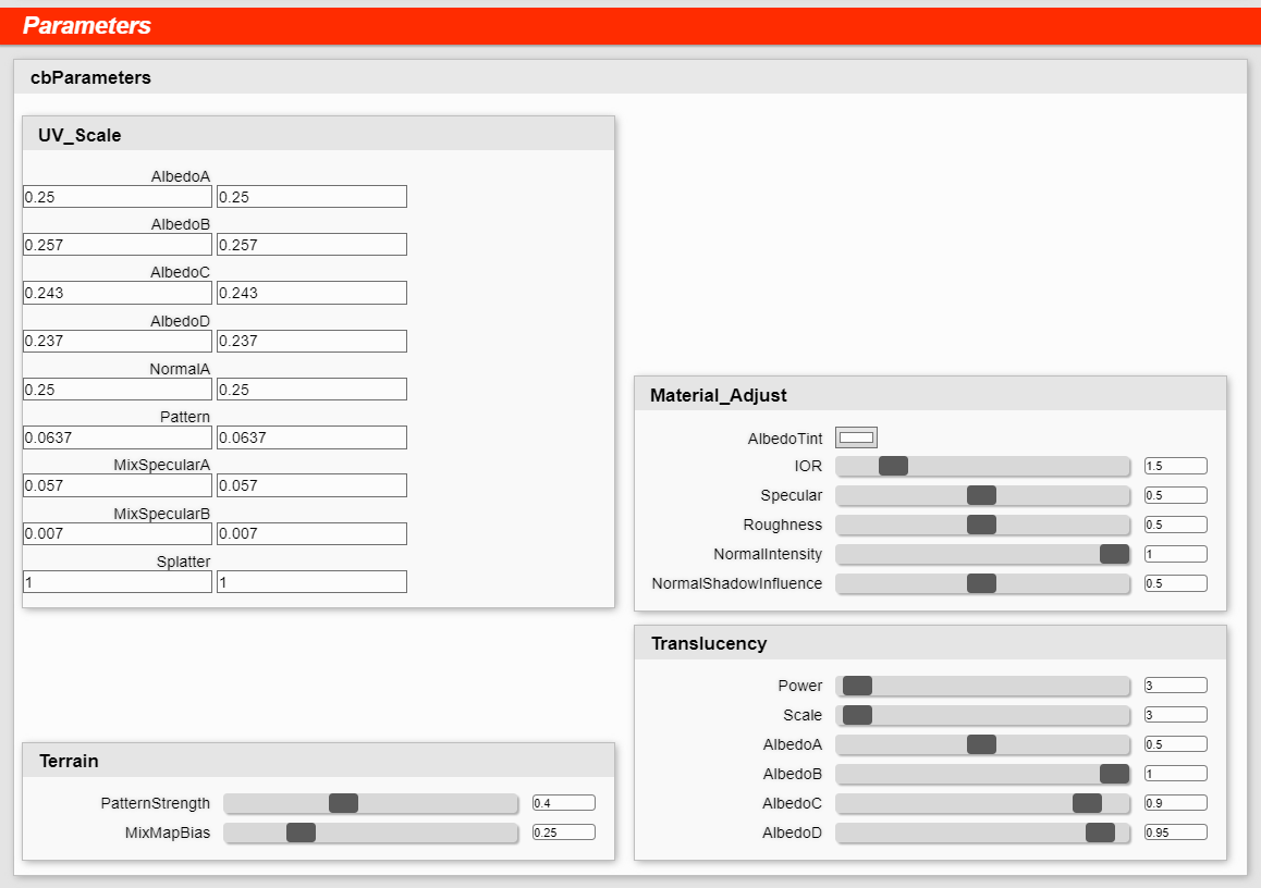
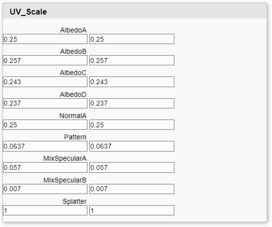
As explained in PBR - Using Standard Shader we can configure which channel each map uses and also scalars for each map. This should be put to great use on the Terrain shader and configure ever so slightly different scalars for each map to break up texture tiling artefacts.
Translucency
A key feature of making the terrain shader look more natural as the sun light goes low is the Translucency options. These expand on the existing options explained here: PBR - Using Standard Shader#UsingStandardShader-Translucency.
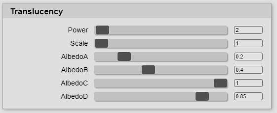
In the Terrain shader there are now additional per Albedo scalars in the Translucency parameters section. These can be used to reduce the effect on areas with out grass for example.
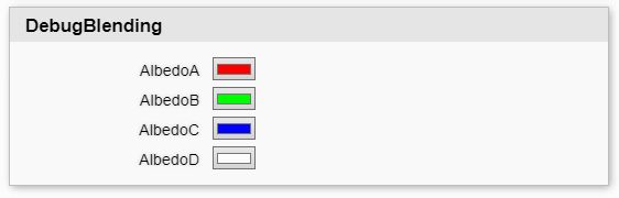
Debug Blending
It can be difficult figuring out exactly which map is blending in where at most times. To make things simpler we have added a "Debug Blending" mode in the Shader Configuration which allows you to see exactly what is going on, by replacing the Albedo Maps with static values. So you can see if you really are getting the split of albedo maps that you desired.
This is intended for development purposes only.

Additionally you may configure these colours to be anything you desire in the parameters section.
Baked Shadows
A concept introduced here is the ability to bake shadows into the terrain. The way this is implemented depends on the blend mode used which is explained in the next section, however the basics are the same.
There will be a mask that it used to say if there should be shadows, and then this mask will follow the same calculations as real life shadows. So if the weather is overcast, there will be reduced shadows.
This can be used to add far off depth to the scene, however it is only recommended for large areas, such as underneath trees. Adding it to areas close to the track will not look good, so it is recommended to fade it out in these areas.
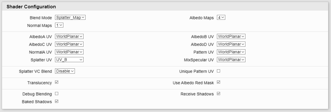
Blend Modes
It is worth noting that the Shader Configuration for the Terrain Shader is a little bit simplified compared to the other shaders. On the Standard Shader and others you can enable or disable each individual map. Here instead we choose a blend mode and the number of albedo and normal maps and that's all. These Blend Modes change which options you have available as explained beneath.
Please Note
Legacy Blend Modes are only available now in the Terrain Legacy shader, and with reduced options to allow a direct upgrade path.
Legacy Layered Blending Mode (IBL Terrain Legacy Shader)
The first blend mode option is the legacy mode, this is similar to the old non pbr terrain shader "Multi layer grass / dirt". It simply makes use of Vertex Colour to blend upto 3 Albedo Maps in.
- Red Channel: Blends from Albedo 1 to Albedo 2 using Mixmap calculations.
- Green Channel: Blends from Red Channel output to Albedo 3 using Mixmap calculations.
- Blue Channel: Blends Pattern Input 1 to Pattern Input2 on a standard linear interpolation scale (Lerp).
The Pattern map in this mode should be made up two channels of overlay data in the red and green channel. Save the texture with a "pt" suffix for this to be saved correctly with texture converter.
This is on offer to allow a quicker way to convert to the PBR shader and uses the same blending logic as the old shader.
Legacy Layered Satellite Blending Mode (IBL Terrain Legacy Shader)
The second option on the old terrain shaders was to use a simple satellite map to multiply details into the entire terrain coverage. This is also available and supports 3 Albedo Maps.
The base blending works the same as the Legacy mode, with all input coming from Vertex Colour.
The difference comes in the Pattern map, which is now used differently.
- This is a linear rgba BC7 map.
- There is a multiplication map in rgb, and an overlay pattern in alpha.
- Save the texture with "mua" suffix for correct encoding.
- There are seperate UV options for the RGB and Alpha channels.
- The multiplication map is always used, and the pattern is blended in by blue vertex colour.
The calculations for blending between maps have not changed from the old shader.
Legacy Blend Blending Mode (IBL Terrain Legacy Shader)
The is the most basic of blending modes.
- It allows two albedo maps and one normal map.
- The albedo maps are blended via vertex alpha.
- The pattern map is applied based on constants on a per albedo map basis.
Splatter Map (IBL Terrain Shader)
As suggested in the titles, the two previous modes are there for legacy support. However the recommended way to do the terrain blending is now through the use of a Splatter Map. Instead of relying on geometry, we now use a map to control our blending. And through the use of tools such as Substance Designer we can now automate the creation of these maps via the use of masks, and even satellite data. These differ from a simple multiplication map of above as they are data inputs in each channel rather than an image input.
The splatter map is in addition to the Pattern Map functions of the Legacy Blending mode although Pattern Blending is now controlled by Vertex Alpha.
It is recommended you setup a UVW Map modifier that is aligned to cover the entire terrain surface. Create a reference object which will not be modified so that you can acquire this UVW mapping at a later date to render masks and more useful information to be able to generate a splatter map.
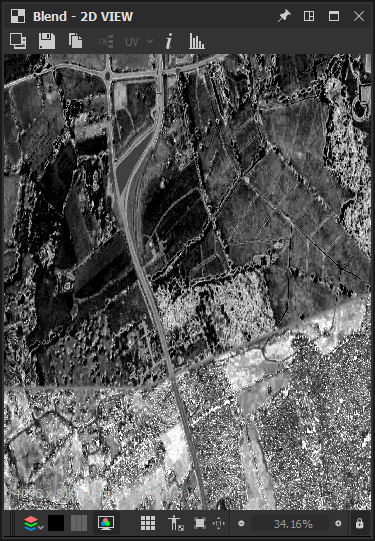
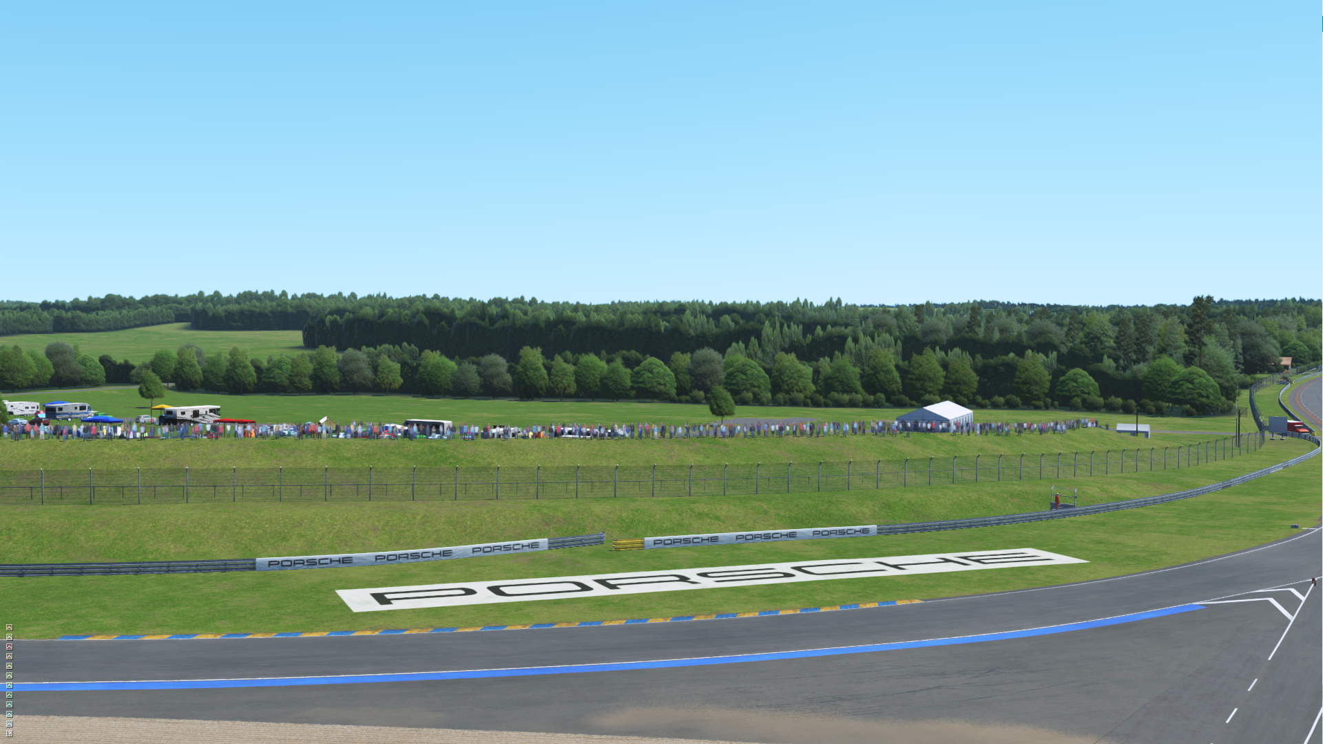
Beneath you can see an example of the splatter map in use, with baked shadows for far off treelines, as well as blending logic generated from satellite image data.
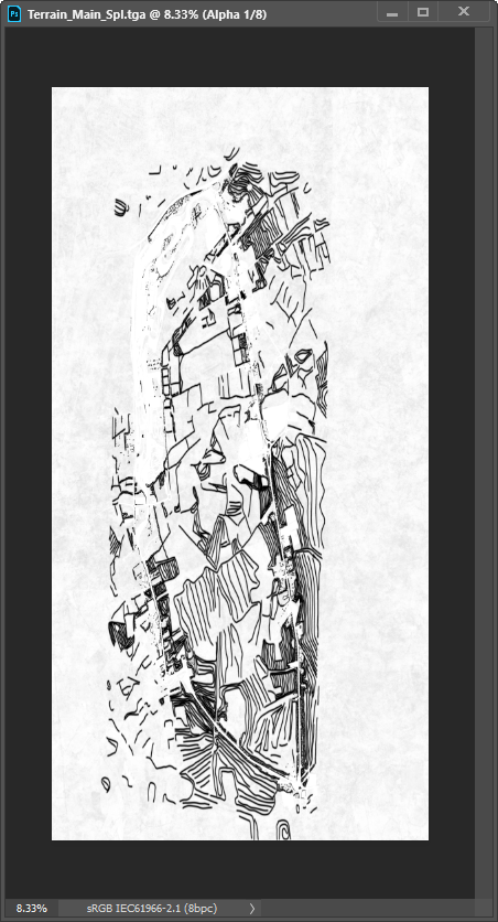
Example Map
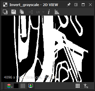
Beneath are examples of the splatter map at Le Mans. On the left is the RGB data, and on the right is the alpha. This is usually setup to cover the entire of the terrain.
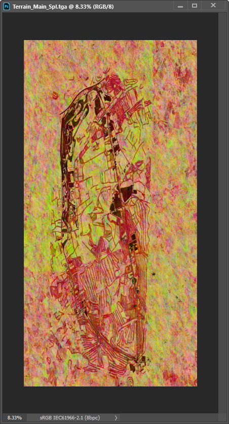
The map basically replaces Vertex Colour painting, and because we can paint on a per pixel detail, we can generate more natural patterns.
The data is used as follows:
- Red: Blends from Albedo A to Albedo B using Mix map calculations.
- Green: Blends from Red Output to Albedo C using Mix map calculations.
- Blue: Blends from Green Output to Albedo D using Mix map calculations.
- Alpha Channel: Shadow Mask.
Extra Options
What's more there are some specific extra Splatter Map options.
![]()
Splatter Vertex Colour Blend
Whilst disabled by default, we can make use of the normal Vertex Colour data to over-ride the map input in certain areas. Say we wish to force a certain map in a certain area, we can do this specifically by using either the Multiply or Detail options for Splatter VC Blend.
The multiply option will multiply Vertex Colour onto the Splatter map. This can help you stop a certain map occurring, but does not allow you to force a certain map to occur. It does not modify your output by default, as Vertex Colour is white by default.
The detail option, will require you to flood fill Vertex Colour with 128, 128, 128 grey before export in order for the Splatter map to work naturally with out adjustment. However as you increase the value used, it will force a certain channel's data to be shown, and as you decrease it will prevent it being shown. For example to force each map only you would fill areas as follows:
- AlbedoA: 0, 0, 0
- AlbedoB: 255, 0, 0
- AlbedoC, 0, 255, 0
- AlbedoD, 0, 0, 255
This can be useful to blend between different materials in different areas with out requiring the need for decal maps.
Unique Pattern UV
Remember that Pattern blending is controlled by Vertex Alpha in Splatter mode.
When this option is enabled, you can specify both unique UV channel data and UV scalar data for each of the two pattern map channels.
This can allow you to have complex blending for mowed grass effects for example. To achieve this you would setup UVW which follows the direction of the mowed grass, and modify one of the pattern maps to make use of this. You would then paint vertex alpha in your model only in the areas you wish for the pattern to be shown. At complicated sections where the UVW doesn't really work, paint back in the generic tiling pattern.
Pattern Random Blend
This option allows the pattern blending to be calculated by a random algorithm and ignore the Vertex Alpha. If there is no specific pattern effect on the grass this can be quite useful. It is enabled by default.
Generating Splatter Maps in Substance Designer
Whilst the above sections explained the functionality of the shader it did not really go into details how to generate such a map quickly and with control over what occurs. We've split that out into a dedicated section.
The major improvement for the use of a Splatter Map is that it's something that we can almost automate the creation of, and setup large variations and realistic grass patterns very quickly. A large amount of this comes down to be able to render out various masks and input them into a Substance Node.
To demonstrate this we will look at how the maps were generated for Le Mans.
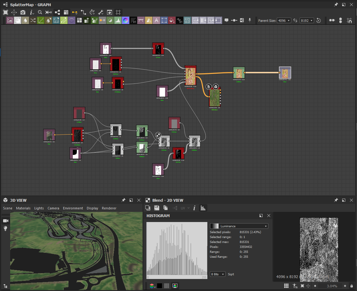
Beneath is a preview of the graph used at Le Mans. The Splatter Map generator has taken a range of inputs, such as masks for where roads are, as well as a saturation map from satellite image data. We even have a preview node shown on the actual 3d model of the terrain to preview what's going on whilst we author the map, although it does not have one to one accuracy with the game, it does make authoring the map initially that bit easier before applying some final tweaks working in game.
Splatter Map Generator
The Splatter Map Generator is included in the Substance Utility Pack
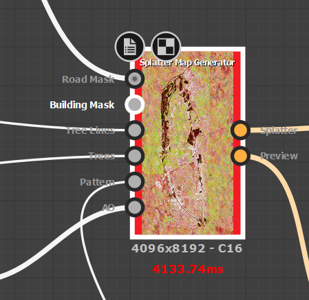
You can specify masks for Roads, Trees and Treelines. These can all be used to force shadows or certain albedo maps to be more prevalent.
Additionally a Pattern input can be specified to increase or decrease the chances of different albedo maps occurring and AO can be baked ever so slightly into the alpha channel.
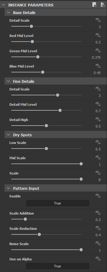
Base Pattern
A base generic pattern is made from various noise inputs. These can be adjusted using the parameters beneath to increase or decrease the chance of a map being used.
On top of the base details, there are some fine detailed noise, and dry spots, which can also be tweaked as desired.
Finally it's possible to specify a single grey scale input which demonstrates on a scale of 0 to 1, if the area should be dry or saturated. This is often generated from satellite map data. The strength of the effect can be scaled on both how much it makes channels more likely and less likely to occur.
Detail Specific Sections
There are various sub sections which help setup different effects.
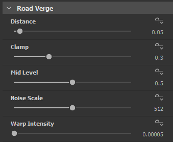
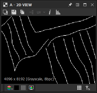
For example the Road Verge allows us to force Albedo A (Dry dirt) near road areas. These settings effect how far from the road and create a randomness to the effect.
The Tree section mostly concentrates on creating reasonable baked shadows through the use of blurs.
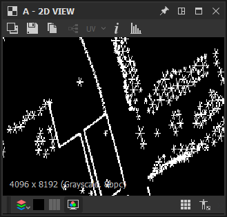
There are separate masks for Treelines and individual Trees, expecting individual lines for each tree line and 6 pointed stars for trees.
These are blurred and combined to create the mask.
We can also use this mask to make certain albedos more or less likely under the trees. In the beneath example we are making the terrain much drier and even bare soil underneath them.
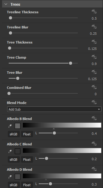
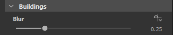
Building Inputs are just used to add to the shadow mask. You can apply some blur to the mask in order to soften the edges.
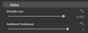
For the alpha section we can adjust how much effect details can add, as well as how much ambient occlusion is blended in. This allows us to add some very basic low level shading to the terrain.
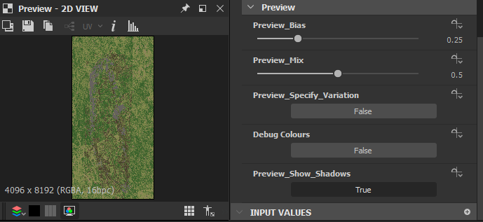
Preview
As well as outputting the Splatter Map, the node can output a preview node. This can be configured beneath, with either realistic colours or debug colours.
Due to using static bias and mixmap values there is likely to be some difference compared to the in game output.
Generating Inputs
The Splatter Map generator takes various inputs, these should be baked either through Substance Designer or through 3ds Max.
To bake these inputs it's often required to acquire the Splatter Map UVW from a reference object and rendering out the UVW information or baking an opacity map from an exported FBX file in Substance Designer.
Basic Mask Rendering
For each these masks:
- Clone all the objects with the required faces to generate the mask
- Merge them into a single object.
- Clean up the UVW by removing all UVW channel data. (Tools - Channel Info, clear each channel). This will reduce the file size.
- Acquire the UVW from your reference object for mapping.
- Render a UVW Mask either through 3ds Max, or by applying a standard material, exporting as FBX and rendering an opacity map in Substance Designer (This is not recommended for Trees).
Tree Mask Rendering
For Treelines the above is fine as long as you render through 3ds Max. This is because single plane meshes for trees don't accurately represent their foot print on the terrain, and the UVW Mapping Render produces an output where Substance doesn't.
For individual trees, we need to clone and rotate the faces by 60 degrees twice.
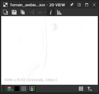
Ambient Occlusion
By rendering Trees and Buildings separately we are effectively taking out the majority of items that would produce some Ambient Occlusion, so our intention with this input is to just input occlusion from the terrain itself.
We can generate this in Substance Designer by exporting an FBX of the entire terrain, importing it and using the bake maps feature.
The resulting output is likely to be very subtle and only make a small difference to the output.
Satellite Map Inputs
Satellite Map Inputs can be rendered out from 3ds Max in the UVW perspective of the Splatter Map.
To do this we take our already previously imported Satellite Maps which were done at the start of asset creation, and acquire UVW from our reference object. Change this UVW to channel 2.
Now we Render this to Texture, outputting diffuse, and use existing UVW Channel 2.
Now we have our Satellite Map rendered out, and we can start to do either edit this in Photoshop or setup some nodes to convert this into some data we wish to use.
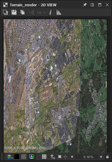
At Le Mans as you can see the sat image was from two separate scans. To make the data work roughly the same over the two, I set up a mask for the two scans, and then exported the saturation of each side of the mask and used levels to even it out, before merging the input.
I then masked out the road sections so that they were 0.5 grey, and put this into the pattern input in the Splatter Map Generator node. This allows for the addition of realistic patterns to the blending. Resulting in the input beneath.