GMT Converter
Overview
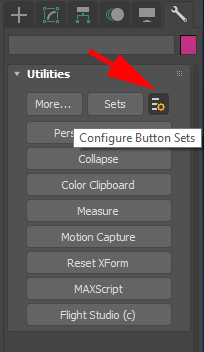
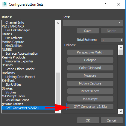
After installing the plugin components as described in the Installation section, open the Max Utility tab (spanner icon), and select the icon shown circled in red in the Max Utility Panel. This will launch the Configure Button Sets dialog. From here, set the number of buttons for the Utility panel, and drag the GMT Converter utility onto an empty button, as shown in the figure. Once completed, your Utility panel should be similar to the one shown in the Max Utility Panel with GMT Converter figure.
The GMT Converter consists of five components:
- The Main Control panel, which allows for global export settings and operations;
- The GMT Output panel, which controls export-specific options;
- The Instance panel, which allows for per-object attributes settings;
- The Scene panel, which is used to create scene (.SCN) files;
- The Animation panel, which is used to export animations.
- The Reflection Mapper panel which is used to setup probes and the objects and export their SCN configuration.
The rollup panels can be rearranged in any order you wish by dragging and dropping to their new location. All Instance panel data settings are saved in the Max file as app data, so once the file is saved, it will require the converter.dlu file to reload. Other configuration-specific settings are saved in the editable file gMotorPlg20.ini, located in the Max PlugCfg directory.
Main Control
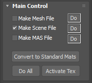
This is the GMT Converter Main rollup has the following options:
- Make Mesh File – selecting this option will cause all selected meshes to be exported as GMT file(s) (according to the GMT Output settings) when either the associated Do button, or the Do All button, is pressed.
- Make Scene File – selecting this option will cause a scene file to be created (according to the Scene Panel settings) when either the associated Do button, or the Do All button, is pressed.
- Make MAS File – selecting this option will cause a MAS file to be created (according to the MAS Panel settings) when either the associated Do button, or the Do All button, is pressed.
- Do Buttons – these buttons are shortcuts to the associated action – they allow you to create mesh, scene, or MAS files without having to go to the associated panel.
- Convert to Standard Mats - this button will convert gMotorMaterials to Standard materials. This can be used if we need to export the scene to a different environment.
- Do All – pressing this button will execute all operations (mesh, scene, or MAS) which are currently selected.
- Activate Tex – pressing this button will refresh texture map rendering in the main viewports if it becomes corrupted.
GMT Output
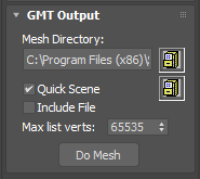
- Mesh Directory – all exported GMT files are output to this directory. Use the Browse button to launch a Folder browse dialog.
- Quick Scene – selecting this option will create a scene file with most setting defaulted to something reasonable, including search paths for meshes and maps. This can be used to quickly export SCN snippets to copy into a master file, be sure to change the Scene File Output setting to Selected in that case. Use the Browse button to launch a File Create/Select dialog.
- Include File – generate the GMT as a C/C++ include file. Not available.
- Max List Verts – maximum number of vertices allowed in a single list. If the number of vertices exceeds this amount, additional lists will be created. This should be set to 65535.
- Do Mesh – convert all selected objects into GMT files.
The GMT Progress panel will appear during mesh conversion, providing stats about each mesh with details of the output geometry, and the option to cancel the conversion at any time.
Instance
The instance data is automatically filled when selecting one or more objects in any Max window.
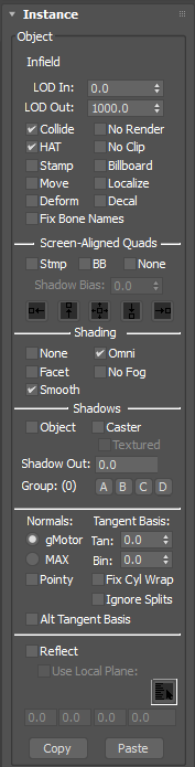
Object Settings
General
- Object Name – read-only name of the selected object – this box will say Multiple Selected if more than one object is selected. You can modify certain attributes on multiple objects.
- LOD In – distance at which the object will switch in.
- LOD Out – distance at which the object will switch out.
- Collide – object is a collision target.
- HAT – object is a HAT (height-above-terrain) object.
- Stamp – object always face the camera, in all three axes.
- Move – object is moveable. Must be checked for object that will be moved so it is exported with a localized origin.
- Deform – object is deformable (allowed to have its vertices modified).
- No Render – object will not be rendered.
- No Clip – object will not be clipped against the back clip plane.
- Billboard - object always face the camera, in yaw (z-axis) only.
- Localize – reset object’s pivot point to be at its centroid.
- Decal – object acts as a decal, which means it will be drawn on top of other nearby (in the Z-sense) objects.
- Fix Bone Names - strips the trailing digits from bone names to allow the use of a common animation file on cloned objects.
Screen Aligned Quads
- Stmp – quad always face the camera, in all three axes.
- BB - quad always face the camera, in yaw (z-axis) only.
- None - quad not billboarded
- Shadow Bias - adjust the shadow bias of billboard shadows
- Alignment Options - adjusts the alignment of the billboard.
Shading
- None – object is unaffected by ambient and directional lighting;
- Facet – object is flat shaded (values are not interpolated across triangle face). This option significantly increases the triangle and vertex count of a mesh, so use with caution.
- Smooth – object is smooth shaded (all values are interpolated across triangle face).
- Omni – object is affected by omni lights.
- No Fog – object is not affected by environmental fog.
Shadows
- Object – object is a shadow object, which means it casts a shadow onto receivers, but is not drawn.
- Caster - object is a shadow caster, which means it casts a shadow onto receivers, and is also drawn normally.
- Textured – the object’s shadow is created by writing the mesh’s z-depth at each pixel into a shadow texture. When Textured is checked, writing of z-depth is masked based on the alpha or chromakey values from the first texture map in each of it’s materials. When unchecked, the z-depth is not masked.
- Shadow Out - set when the shadow lods out. This will overwrite the scene value only if it is lower.
- Shadow Groups - set which shadow settings this object casts shadows on. More information can be found here.
Normal Options
- gMotor – if selected, vertex normals are computed during conversion using weighted average face normals. No smoothing groups are used and it is required for smoothing groups to be detached to elements.
- MAX - if selected, internal Max vertex normals are used. Vertex normal generation using Max normals has been improved significantly. When using Max vertex normals, the EditNormals modifier (if available on the modifier stack) is now supported to allow for very precise vertex normal adjustments. Also, smoothing groups are automatically supported. However this can result in increased draw calls on the exported mesh, so be careful with it's use.
- Pointy – if checked, all normals point straight up – this can be used to uniformly light stamp and billboard objects. Using the Pointy Normals setting will override any other normal generation.
- Tangent Basis –
- Binormal Basis -
- Fix Cyl Wrap – if checked, an alternate method is used to export texture coordinates, which can correct texture mapping seams on cylindrical objects. This option should rarely be required
- Ignore Splits
- Alt Tangent Basis
Tangent Generation
Tangents are generated by using the UV channel specified in the Normal Map stage. The specified UV channel may not be necessarily exported with the GMT though, if the slot is the 5th or higher, and the selected UV channel is not specified in the earlier slots.
Reflections
- Reflect – if checked, the object(s) will be reflected about the global reflection plane (as specified in the Scene Panel).
- Use Local Plane – this option is only available for objects set to reflect. If checked, the selected objects will use a local reflection plane instead of the scene’s global plane. The local reflection plane can be set by:
- Selection Gizmo – clicking this will present a list of objects to be used as reflection planes (objects whose name contains RefPlane.)
- Manually type in the reflection plane coefficients (you probably don’t want to do this for a local plane.)
- Copy / Paste – used to copy and paste attributes from one set of selected objects to another.
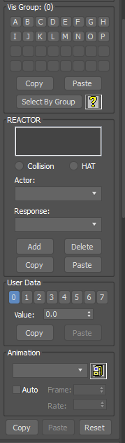
Vis Group Settings:
Visibility (vis) groups are used to group objects together – these groups of objects can then be made visible or invisible according to various in-game settings. More information can be found here.
- Vis Groups A – P – assign selected object(s) to the chosen vis groups.
- Copy/Paste – used to copy and paste vis group settings from one set of selected objects to another.
- Select By Group – get the attribute setting for the objects in the chosen vis groups.
REACTOR Settings
The REACTOR is used to execute a response when a specific actor interacts (either by collision or height-above-terrain). Typically we do not set these up in the plugin.
- Reaction List – list of available reactions
- Collision / HAT – shows whether the selected reaction is a collision or HAT reaction.
- Actor – select an actor to set up a new reaction, or shows the actor for the current reaction.
- Response - select a response to set up a new reaction, or shows the response for the current reaction.
- Add - add a new reaction to the reaction list, created from the current Actor and Response.
- Delete – deletes the reaction currently selected in the reaction list.
- Copy / Paste – used to copy and paste reactor settings from one set of selected objects to another.
User Data
There are upto 8 user data values that can be specified per object. This data will then be used for some function by either the game or shader.
Animation
- Animation File – .ANM file to apply to the selected instance(s). Use the Browse button to launch a Find File dialog.
- Auto – check to run the animation automatically in cycle mode.
- Frame – start frame if Auto is selected. Can be used to offset the starting frame for multiple similar anims to get a more random effect.
- Rate - the speed to play through the animation.
Instance Data Control
- Copy - Copy the instance data to the clipboard
- Paste - Paste a previously copied set of instance data to the selected objects.
- Reset – remove all object-specific app data from the Max file. Use with caution, as all settings for this node will be lost, even app data from non-gMotor plugins.
Animation
The animation rollout can be used to generate a ANM file which can then be applied to selected instances in the Instance rollout. Only a single set of export parameters are saved per scene.
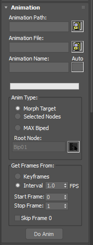
General Settings
- Animation Path – all exported ANM files are output to this directory. Use the Browse button to launch a Folder Browse dialog.
- Animation File – the file name for the current ANM file. Use the Browse button to launch an Open File dialog to set the file name, type in the name, or use the Auto button to set the name based on the Max file name.
- Animation Name – the name of the current animation, used by the application to locate the animation. Type in the name, or use the Auto button to set the name based on the Max file name.
- Auto – when pressed, the Animation File and Animation Name are automatically set based on the Max file name.
Anim Type
- Morph Target – not currently implemented;
- Selected Nodes – animation frames are extracted only from the selected scene nodes. This is useful for animation which do not use a hierarchical bone structure
- MAX Biped – animation frames are extracted from a hierarchical bone structure such as a Biped.
- Root Node – use the Select Object button to choose a root node from the scene. If using Selected Nodes, the root node must be the mesh to which the selected bones are attached. If using MAX Biped, the root node must be the topmost bone in the hierarchy, e.g., Bip01.
Get Frames From:
- Keyframes – animation frames are extracted only from keyframes.
- Interval – animation frames are extracted from keyframes, and interpolated if necessary, to create an evenly spaced series of frames at the specified Interval. Not currently implemented.
- Start Frame – the first frame from which to extract animation data.
- Stop Frame – the last frame from which to extract animation data
- Skip Frame 0 - the played animation will not use frame 0.
Do Anim – in the case of either Seleceted Nodes, or MAX Biped, the mesh to which the bones or skeleton is attached must be selected, then press Do Anim to extract animation frames and create the ANM file.
Scene File Output
This roll out allows the configuration of a full SCN output. In practice we just output the selected Reflection Mappers, Instances or Omni lights to a temporary file and copy them into a manually maintained master scene file.
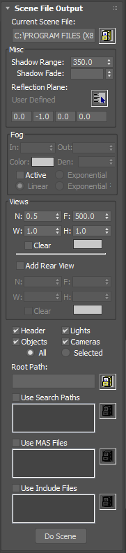
Current Scene File – path of the current scene file. Use the Browse button to launch a Find File dialog; you may also enter a file name manually.
Misc
- Shadow Range – shadow casters or object beyond this range will not be shown. Default is 350.0, we use around 500 - 700m in practice depending on circuit though.
- Shadow Fade - fade out shadows at this distance
- Reflection Plane – the global reflection plane used for any objects set as Reflect, and which do not have a local reflection plane. The default is a plane with the coefficients (0.0, -1.0, 0.0, 0.0), which represents a plane parallel to the x-z plane at y = 0.0, pointing upwards. The global reflection plane can be set by:
- Selection Gizmo – clicking this will present a list of objects to be used as reflection planes (objects whose name contains RefPlane.)
- Manually type in the reflection plane coefficients.
Fog
A lot of these settings are legacy and may not work.
- In – distance from eye at which fog begins.
- Out – distance from eye at which fog ends.
- Color – color of the fog.
- Den – fog density, used instead of Fog In / Fog Out. Only applies to Exponential or Exponential² modes.
- Active – activates fog for the scene, using one of the following fog modes:
- Linear – interpolates fog color linearly from the Fog In distance to the Fog Out distance.
- Exponential – interpolates fog color exponentially according to density setting;
- Exponential² – interpolates fog color squared exponentially according to density setting;
View Settings:
- N - near plane distance
- F - far plane distance
- W - viewport width; if less/equal to 1.0, the number is a percentage of the current video mode width
- H - viewport height; if less/equal to 1.0, the number is a percentage of the current video mode height
- Clear - toggle to clear viewport background. Use the Color swatch to select the background clear color.
- Add Rear View - check to add a second view as a child to the main view; this second view is set up the same way as the main view.
General
- Header – include Fog and View settings in the scene file.
- Objects – include Max mesh objects in the scene file.
- Lights – include Max lights in the scene file.
- Cameras – include Max cameras in the scene file.
- All / Selected – for each of the above sections, include either all objects of the specific type, or only objects which are currently selected.
- Root Path – this path will be removed from all full paths used in the scene file (making them relative paths). The assumption is that a root path will be provided by the application to allow for asset loading from any install directory. Use the Browse button to launch a Browse for Folder dialog.
- Use Search Paths – if checked, any search paths specified in the associated list will be added to the scene file. Use the Browse button to launch a Browse for Folder dialog.
- Use MAS Files – if checked, any MAS files specified in the associated list will be added to the scene file. Use the Browse button to launch a Find File dialog.
- Use Include Files – if checked, any include files specified in the associated list will be added to the scene file. Use the Browse button to launch a Find File dialog.
- Do Scene – create the scene file.
Reflection Mapper
The reflection mapper allows the configuration of reflection probes. These are then exported with any SCN export.
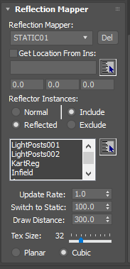
- Reflection Mapper - Here you can select from existing mappers, use the drop down to create a new one or delete a mapper.
- Set Location - You can set the location of the mapper by either manually entering the co-ordinates, or using the option to select an object and it's pivot point will be used.
- Reflector Instances - Here we can select which instances are either included or excluded.
- Update Rate - This sets how many times a second the probe is updated.
- Switch to Static - After this distance the probe is not updated
- Draw Distance - This sets the maximum draw distance for the probe, any objects included but further away than this will not be rendered.
- Tex Size - This sets the size of the output probe.
- Type - Set if the probe is planar or cubic.