Roads - Modelling & Mapping
Mapping Race Groove
Beneath are instructions for mapping race groove.
This is a process which is required to make the mapping of the racing line follow where the racing line usually is.
Please note that this process is for a single layout track.
For tracks with multiple layouts you may need to map some sections multiple times and duplicate the meshes. It's usually best to just create small sections with the unique areas, and just live with the road seam issues in this case.
Requirements
- You have finished modelling all roads and curbs and do not intend to add any more.
- You have split up outer roads and they use unique materials with real road disabled for optimisation.
- An AIW has been created to import the fast path.
Steps
- Join ALL road, curb and other meshes that use race groove into a single object.
- Objects outside of the driveable area should use materials with race groove settings disabled.
- Weld up the verts on Roads, but do NOT weld on the curbs or you will break smoothing.
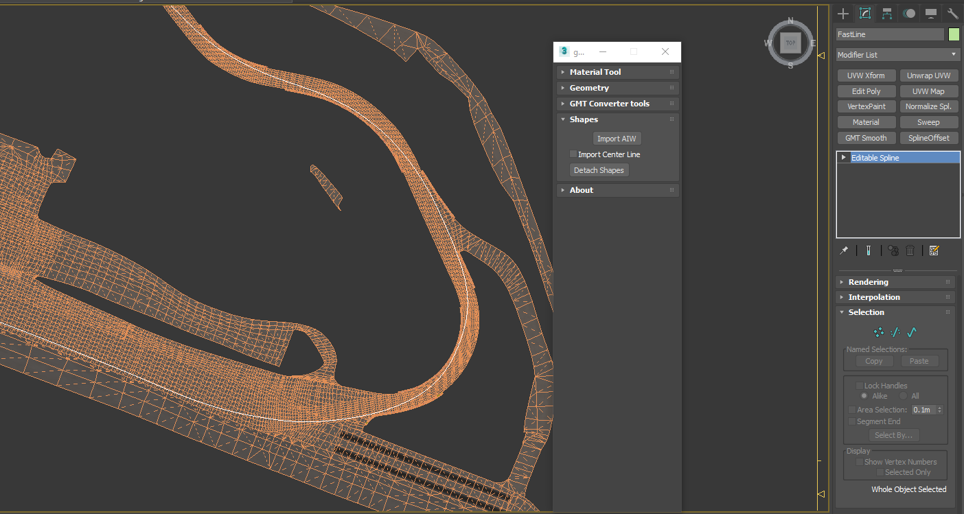
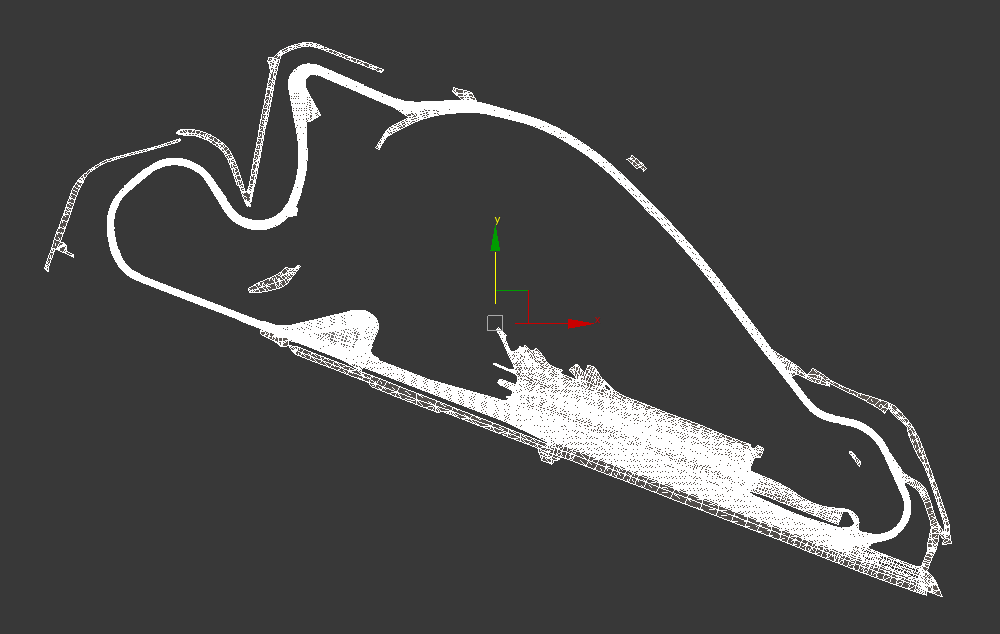
- Import the Fast Path by using the GMT Material Script. ( http://www.mj-multimedia.net/2012/03/gmaterial-tool-for-3dsmax/ )
- Do a little tidy up on the path by using soft selections to pull the line away from curbs a little.
- Soft Selection Tip: use 0.3 for Pinch and Bubble to get a linear selection.
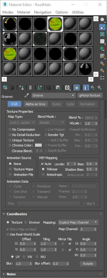
- Configure the race groove to be visible in the Material Editor
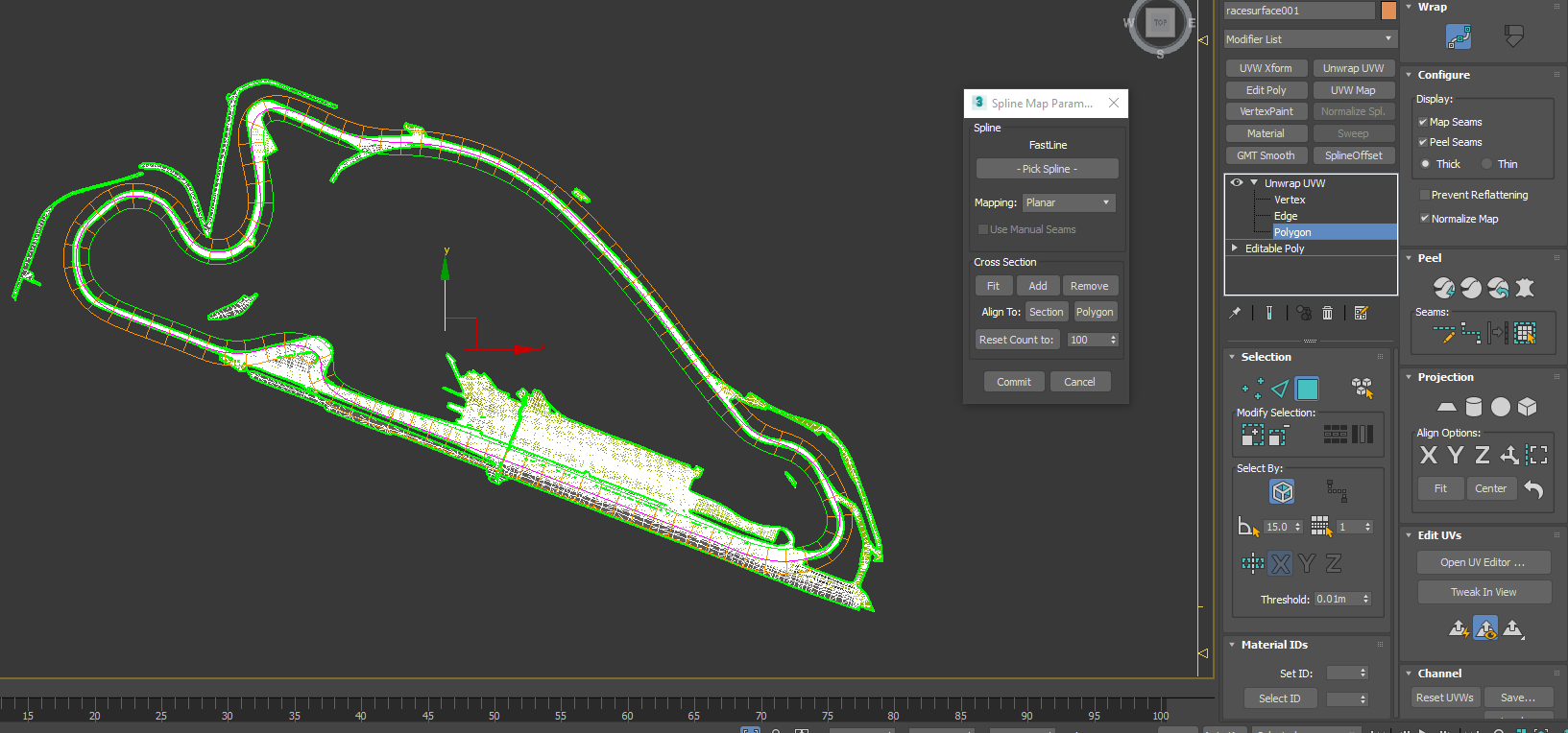
- Add a UVW Unwrap Modifier onto your combined race surface object
- Set the UVW channel to the same channel as the groove. (Typically channel 3). If asked to move UVW select abandon.
- Select Polygon submode, and ensure there is no polygon selection active. We want to apply this everywhere.
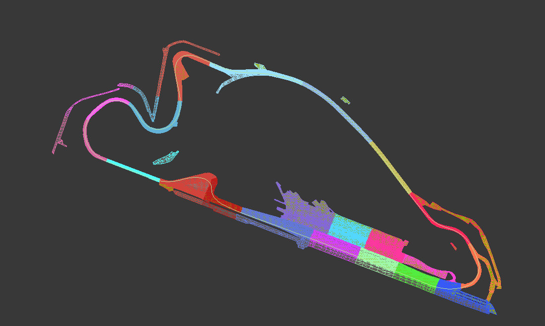
- Choose the spline mapping option under the wrap mode.
- Under the Spline Map parameters options, pick the FastPath spline, and set the mapping to planar.
- Under cross section reset count to a number to ensure you have an even number of segments.
- Select all the sgements and use the scale option to reduce their width to about 15m.
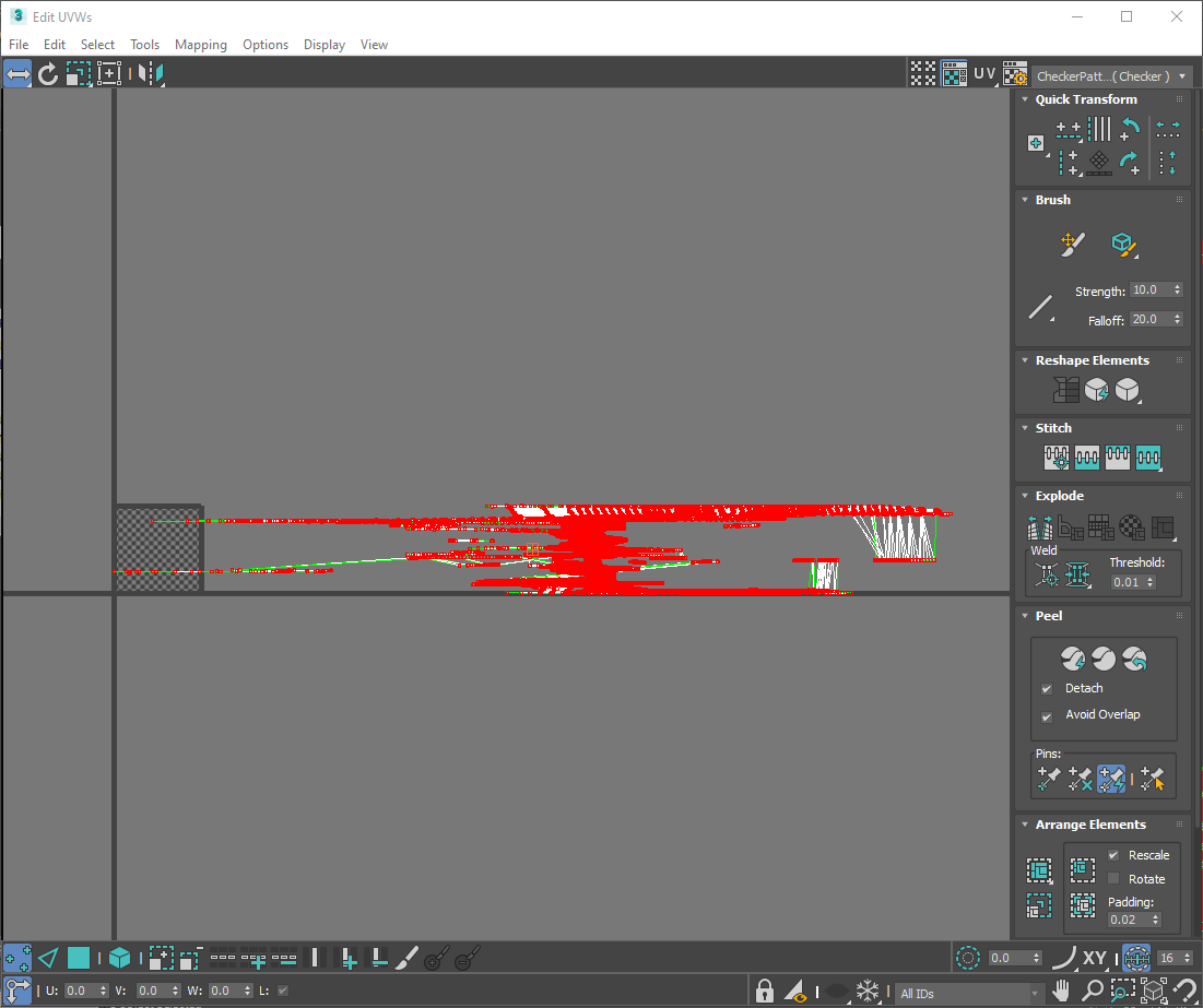
- Inspecting the UVW unwrap, we can see that the mapping goes from 0 to 1 on the V axis. and spreads out along the U axis.
- We need to adjust the mapping to match our map and so that it tiles appropriately
- Our race groove map is centred along the middle with different effects away from the racing line.
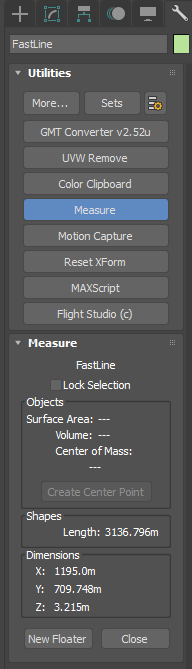
- Use the measure tool to measure the length of the fast path. Divide this number by 40m for a normal race track. And we will use this for our tiling on the length direction.
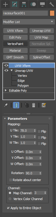
- Add a UVW Xform to correct the UVW.
- We need to apply this to the entire object and set the channel to 3.
- Add a 90 degree rotation since our map goes along the U axis rather than V.
- Set the U Tile to the value we calculated before, but round it to a whole number so the tilling is continuous.
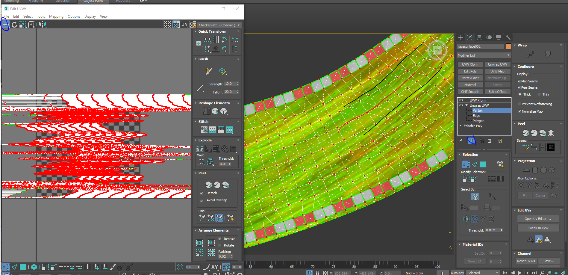
- We now need to centre the path by going back to the UVW unwrap modifier
- Ensure that you can view the final output, and then we need to move the mapping on the U axis so that it is centre aligned.
- We can see an area in the map where there are no skid marks, we need to move this into the middle of the fast path.
- If you can export the mesh and preview it's effects in the scene viewer.
- On large tracks however you may need to split the object up or just delete some sections with an EPoly modifier to keep under the maximum vert list size for an object.
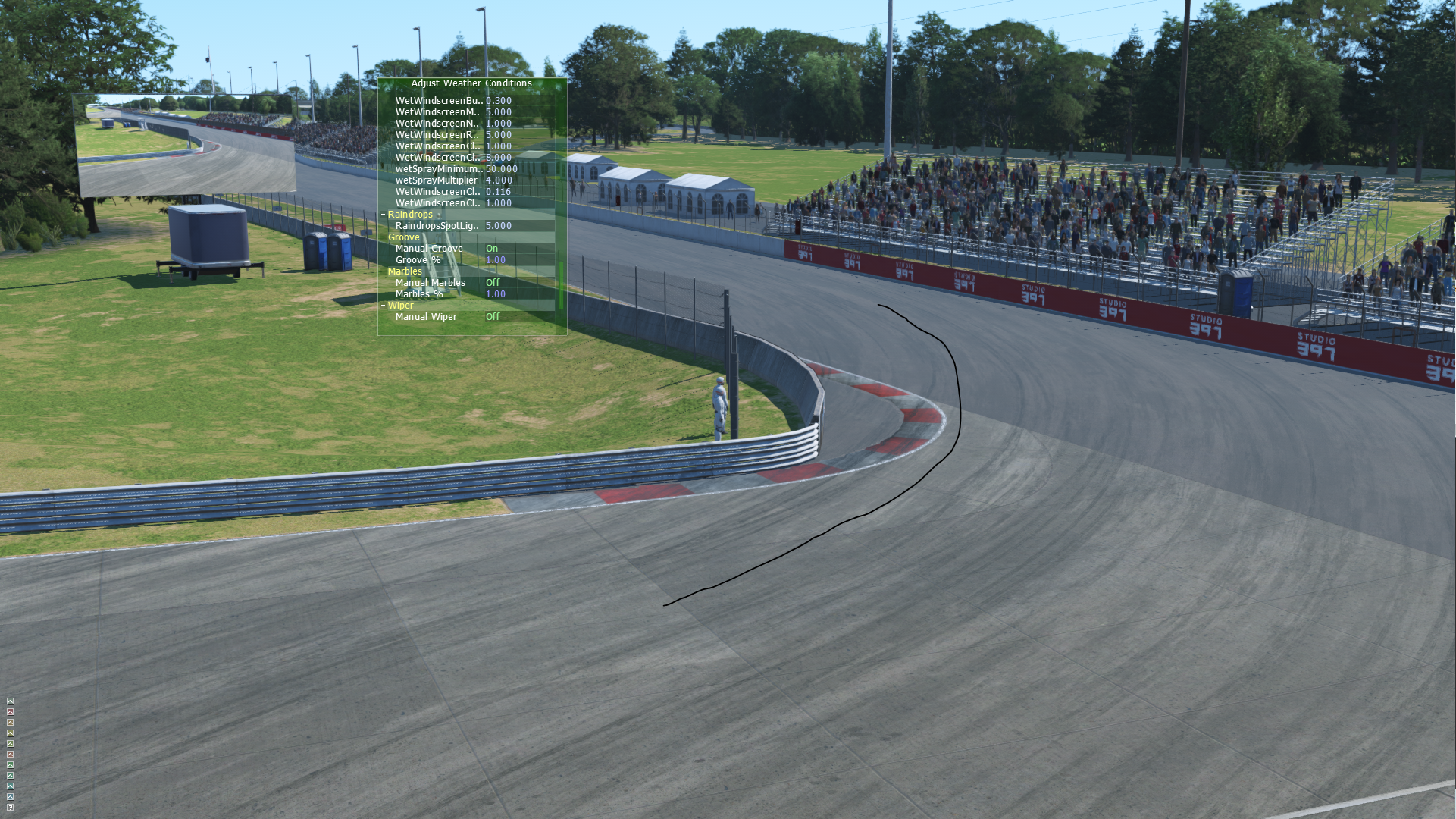
- In the SceneViewer use the Weather dialogue and set manual groove. This allows you to see with groove everywhere
- Note that the we have skid marks showing in most places, but not directly on the racing line.
- If you are not happy with the mapping go back and tweak. It's important to get it right before object splitting.
- The final task is to optimize the object split.
- Collapse the modifier stack and then split up the road into sensible splits.
- Remember that road splits are often dictated by the number of omni lights and object size. See Object Optimization for more information.
- Try to avoid splitting curbs up or other objects with specific smoothing setups.