Rain Effects and Windscreen Shaders for Cars
Table of Contents
Introduction
Goal of this guide is to help the artists in the process of implementing rain effects for body parts and windscreen, for both exteriors and interiors views.
Requirements
Software
- 3D Studio Max 2012 with the lastest rFactor 2 plugins
- Photoshop CC 2018
- NDO2/Quixel Suite
Assets
- Car body needs to be mapped.
- UVW template of the car body @ 4K resolution.
- Car Wiper Animation fully implemented and ready.
- rF2_CarRainFx_Template.zip (click to download the zipped .PSD template)
- raindrop_desc.json (click to download the template)
Step 1 - Implementing Rain Drops Effects in the Body Parts
1.1 - How it works
The dynamic rain effects are composed by different elements (drops, streakes etc) that are being rendered on the Diffuse Map UV channel (CH1). This means the artist doesn't need to create any specific UV mapping for this effect, but all we need is a color map to tell the engine what islands in the mapping are referring to Top, Left, Right and Front/Back body parts. Colors are:
- RED (255,0,0) ; TOP
- GREEN (0,255,0); RIGHT
- BLUE (0,0,255) ; LEFT
- YELLOW (255,255,0); FRONT/BACK
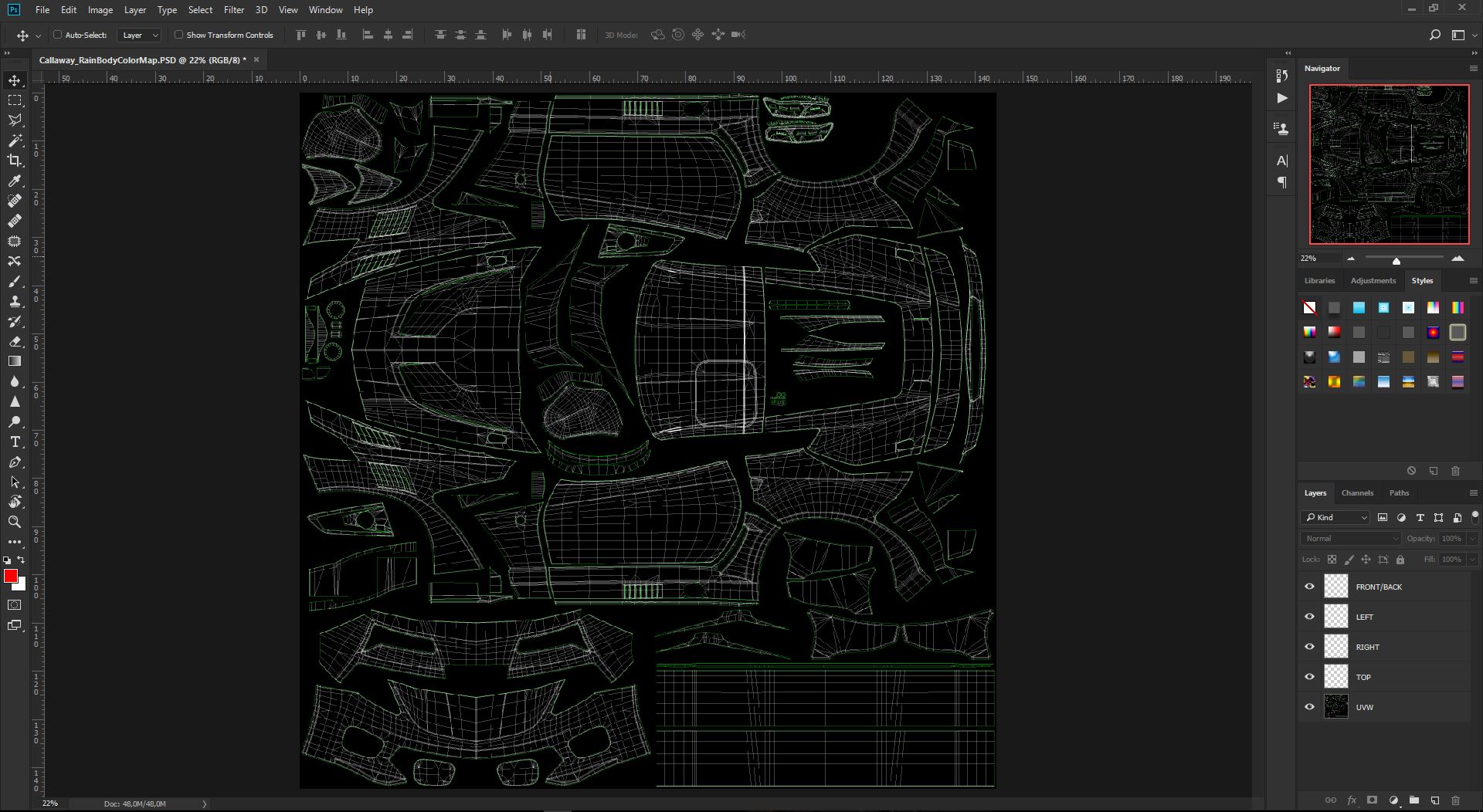
1.2 - Creating the Body Rain Map
- Open the UVW Template of the car body you are working on,
- Save the file as "CarModName_RainBodyColorMap.PSD"
- Create a New Layer and rename it as "TOP Parts"
- Create a New Layer and rename it as "RIGHT Parts"
- Create a New Layer and rename it as "LEFT Parts"
- Create a New Layer and rename it as "FRONT/BACK Parts"
You can now select the "TOP Parts" Layer and using the Polygonal Lasso Tool, start creating masks for every island which is TOP projected.
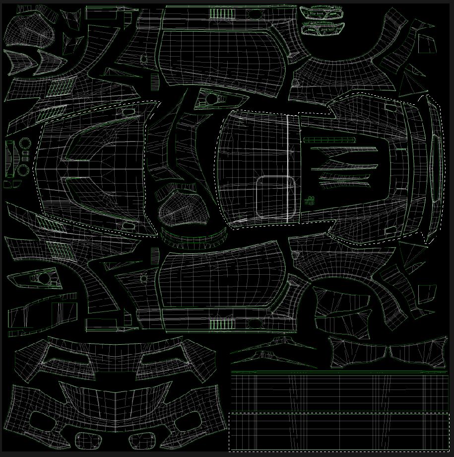
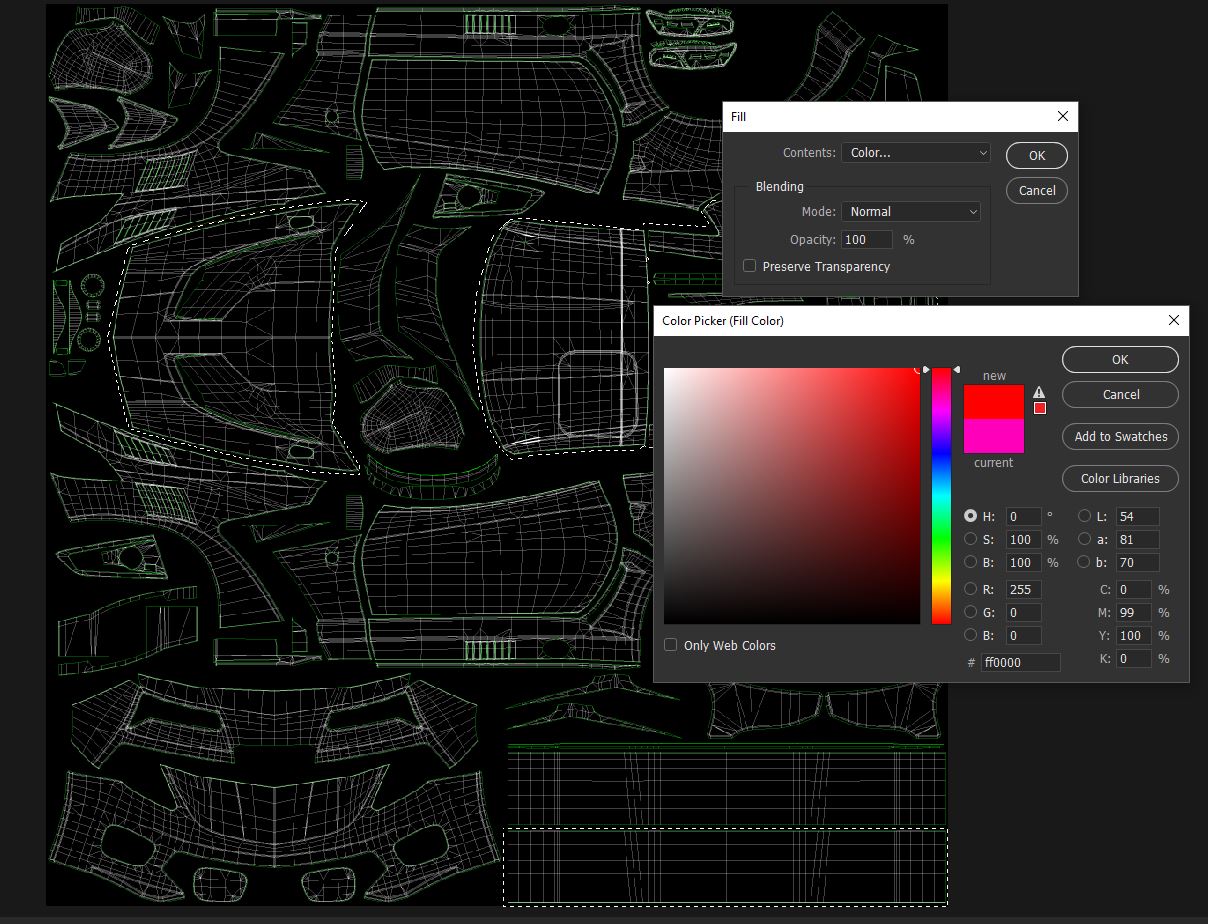
Use the SHIFT key to create multiple selections. Once you have all your selections ready you can press SHIFT+BACKSPACE (FILL) and then set the dialog; Contents to COLOR, Mode set to NORMAL, Opacity set to 100%. Pick the RED color from the color picker (255,0,0) and press ok to fill all the selections with RED color
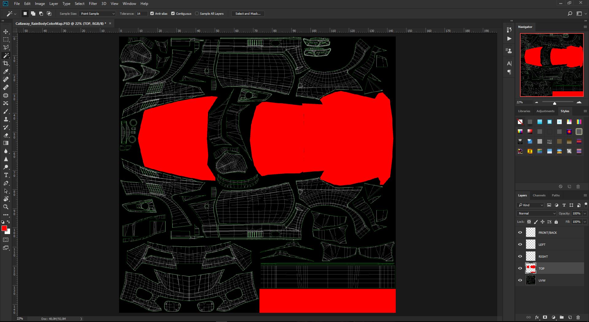
You can now select the "RIGHT Parts" Layer and using the Polygonal Lasso Tool, start creating masks for every island which is RIGHT projected. Use the SHIFT key to create multiple selections. Once you have all your selections ready you can press SHIFT+BACKSPACE (FILL) and then set the dialog; Contents to COLOR, Mode set to NORMAL, Opacity set to 100%. Pick the GREEN color from the color picker (0,255,0) and press ok to fill all the selections with GREEN color
You can now select the "LEFT Parts" Layer and using the Polygonal Lasso Tool, start creating masks for every island which is LEFT projected. Use the SHIFT key to create multiple selections. Once you have all your selections ready you can press SHIFT+BACKSPACE (FILL) and then set the dialog; Contents to COLOR, Mode set to NORMAL, Opacity set to 100%. Pick the BLUE color from the color picker (0,0,255) and press ok to fill all the selections with BLUE color
You can now select the "FRONT/BACK Parts" Layer and using the Polygonal Lasso Tool, start creating masks for every island which is FRONT or BACK projected. Use the SHIFT key to create multiple selections. Once you have all your selections ready you can press SHIFT+BACKSPACE (FILL) and then set the dialog; Contents to COLOR, Mode set to NORMAL, Opacity set to 100%. Pick the YELLOW color from the color picker (255,255,0) and press ok to fill all the selections with YELLOW color
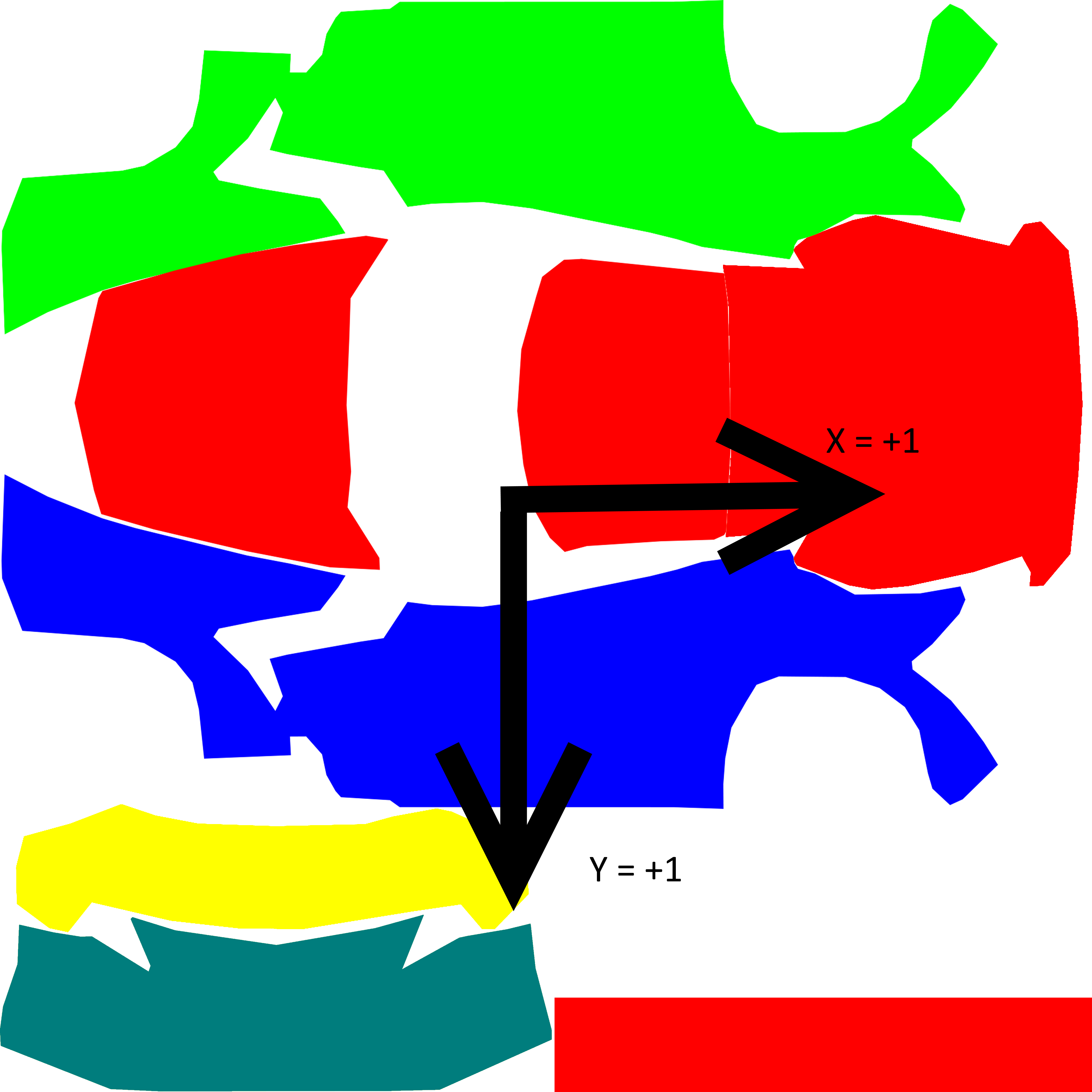
You should now have something like this:
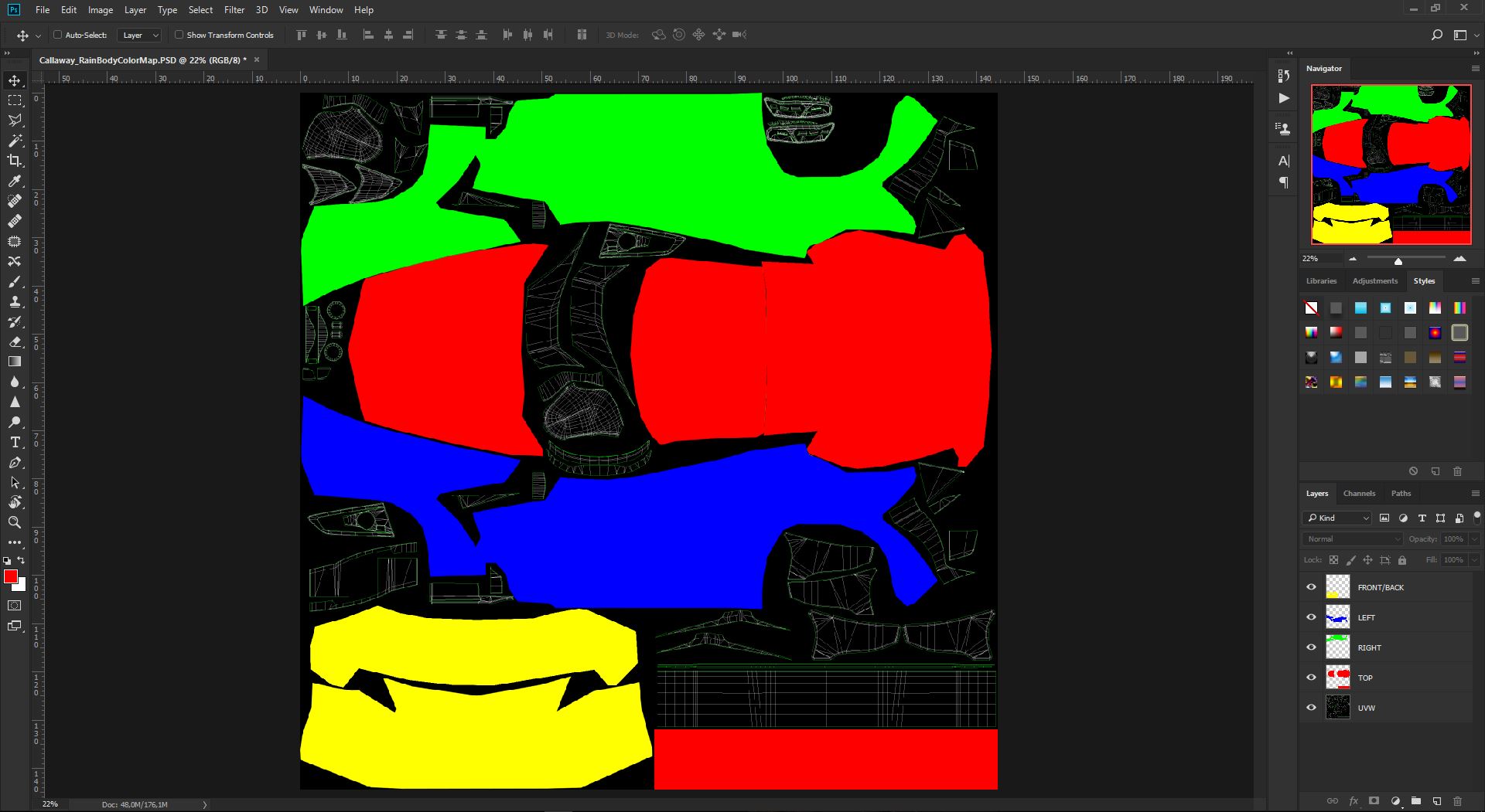
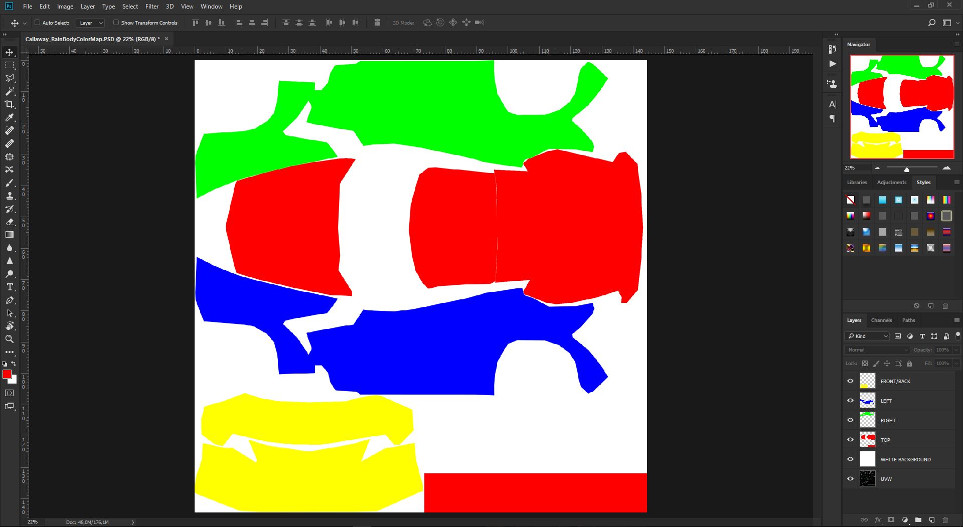
At this point you are almost ready. The last step is to create a White Background for the final map, and this is easily done by creating a new Layer, just above the UVW base, and fill it with full White (255,255,255) color. You should now have this:
The document is now ready to export the Map, but before to do so let's save the .PSD for any future usage and archive.
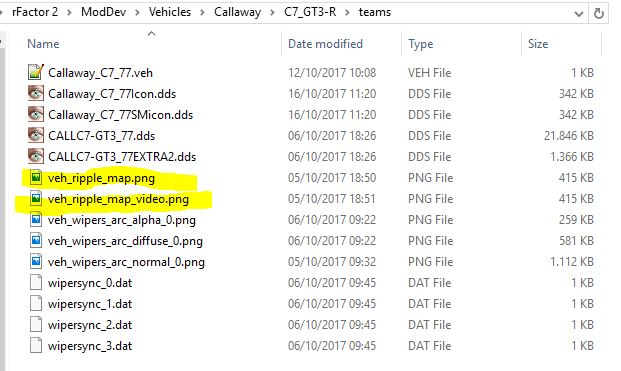
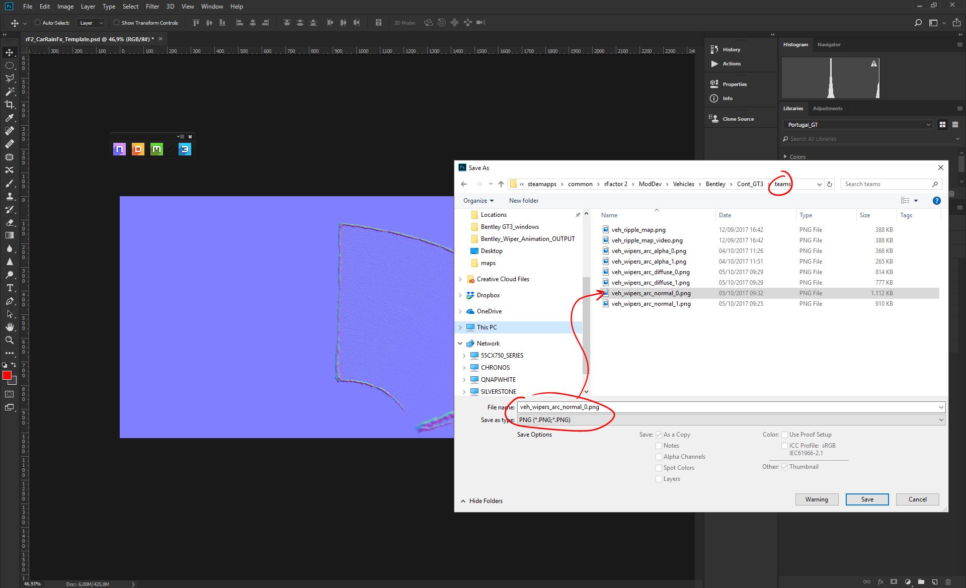
We need 2 identical maps, with a size of 512*512px (you need to downsize the template map before to save these maps, but keep the 4K source for any other future usage and livery), with same attributes, just saved as two different files. Both files needs to be saved into the "teams" folder of the specific car mod we are working on.
Save As (default settings); veh_ripple_map.png
Save As (default settings); veh_ripple_map_video.png
You now can create the .json descriptor file for the ripples.
For each car in the /team/ folder (where the other rain textures are) there should be a raindrop_desc.json file (template is attached).
This .json says to the game: "When a ripple starts in the area of the color X, it goes in the following direction ..."
The ripple direction is expressed in texture coordinate, i attach the map with the texture coordinate (positive X go right, positive Y go down).
PIC BASE:
Let's take a look at the raindrop_desc.json file
If you open the raindrop_desc.json file you'll see the following text:
"Desc":
{
 "NumberOfSets": 1, ? this is the number of different colors that are on the map (usually 5 is
 enough: TOP/LEFT/RIGHT/FRONT/BACK, 8 should be the upper limit)
 "MinLengthSqrt": 0.25 ? this is the minimum intensity where the effect shows up (leave it like this)
},
"Set_1":
{
 "Color": ? when a raindrop falls on the color specified here ...
 {
 "R": 255,
 "G": 0,
 "B": 0,
 },
 "StillDirection": ? ... draw a ripple in this direction when the car is still ...
 {
 "X": -1.0,
 "Y": +0.0,
 },
 "MovementDirection": ? ... or interpolate to this direction when the car is moving.
 {
 "X": +1.0,
 "Y": +0.0,
 },
 "Description": "Top"
},
Example:
Given the previously described raindrop_desc.json and the following ripple texture:

Let's take a look at how it behaves ingame:
Let's suppose that a ripple is randomly generated in this location X

It fell on the BLUE color, the game checks the raindrop_desc.json file for the blue color but it doesn't find it (because in the example we set NumberOfSets to 1).
This FAILS, the ripple is not drawn.
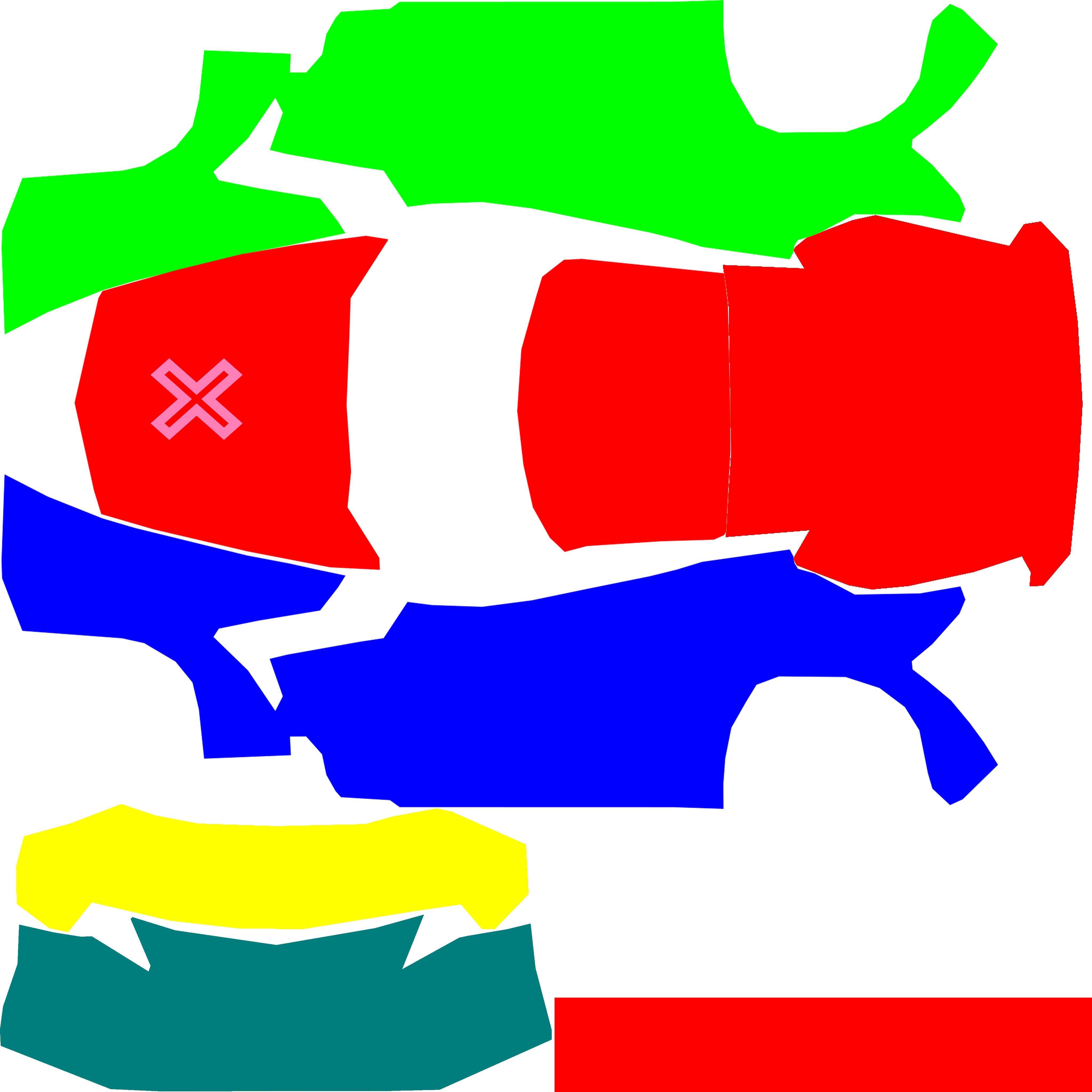
It fell on the RED color, the game checks the raindrop_desc.json file for the red color, it doesn't find it!
Let's suppose that the car is not moving, the game reads StillDirection from the json file to create a ripple moving in that direction.
The StillDirection is set to (-1.0, 0.0), so this will be the resulting ripple ( take in mind PIC BASE):

Let's suppose that the car was moving instead.
The game reads MovementDirection (depending on the speed of the vehicle) to create a ripple moving in that direction.
Since the MovementDirection is (1,0) this will be the resulting vector ( take in mind PIC BASE):

Step 2 - Implementing Rain Drops Effects in the Windscreen IN and OUT
2.1 - How it works and Goals
The RainFX on the glass has a dedicated code that does use a group of Maps (Wiper Arcs, Diffuse and Normals) to render all the various elements of the effect, respecting the wiper kinematics. The Art involved needs to be extremely constant and streamlined, since our underneath presets are expecting specific raster inputs to drive the effect as its best. Artists are free to experiment and introduce dedicated art per car, but we do suggest to use our RainFX Template as a base, which has been developed on top of the effect preset and have been deeply tested. If you introduce new art, please, be sure it's 100% compliant with the original requirements (contact the responsible of the Art Direction for any further information). The Shaders targeting such technology are called "Windscreen Inside Shader" and "Windscreen Outside Shader".
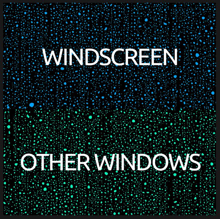
We do have a 4K rain drop diffuse (this is core material, not moddable) that we do use to map our different glass parts. Since the code it's treating the different bit of glass in a different way (windscreen it's being worked differently than side windows), we have subdivided such 4K texture in 2 different areas, where the engine it's expecting to find always the same glass parts - to apply the dedicated rain dynamics. This is a schematic of the map, showing the 2 different areas of the UVW, where you have to map your car glass parts;
We also have the Diffuse Map/s, that are needed to introduce the Art details for the water that does accumulate inside the Arc Masks areas. They are basically Grayscaled images, with the white being rendered as water effects, and with the black being ignored as clear areas. Every time the wiper will pass in that Arc area, it will clear the previous pass of effects, and a new pass will start at the same time. We have various level of randomness to avoid event repetitions, and most of them are controlled by the code, and you don't have to worry about. Only randomness element we can control, is in the diffuse white levels, since we have a threshold that it will pick a different alpha strenght in the map at every pass, so that we will see the same events happening at different strenghts on the Windscreen.
We do suggest to re-use our RainFX Template, since we need constancy along different cars (we wouldn't want each cars to have different rain graphics). If the Template art it's hard to reuse/adapt, we do suggest to just mimic what have been done, so the we do achieve constancy, reducing at the same time any untested situation.
In order to achieve constancy between all cars, and also between the two different POV (inside and outside), we have to streamline as much as possible the way we work these UV maps.
These are core points to achive our goal:
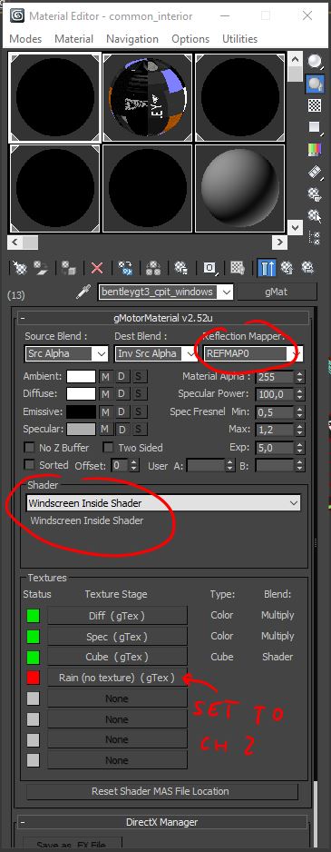
- Always use the dedicated Shaders for the car Glass parts; "Windscreen Inside Shader" and "Windscreen Outside Shader".
- Always use the livemapper and REFMAP0 for all the Glass parts.
- Always maximize the usage of the canvas. Keep in mind that the average real world size of the texture is 2mt*2mt, so this means that most of the time your (average car) windshield will use the entire area on the top.
- Always map both Glass interior and exterior mesh, at the same time, and 100% same mapping, so that you get constancy between the effect, when visibile from the outside as well as what you get when sitting in the cockpit.
- Always respect scaling between parts; NEVER change the world scale between the different UV islands on the map. This will avoid rain drops looking of different sizes along the different glass parts.
- Use BOX projection at constant scale.
- If the car has a back glass, you can put this on the bottom area of the UV canvas, respecting same rules listed above.
2.2 - Shader and Materials Setup
We'll be using these settings for both Inside and Outside shaders:
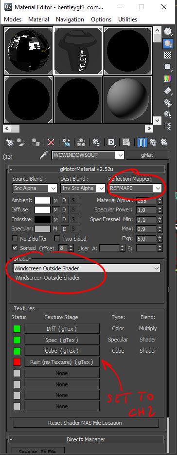
PS: For the open wheelers, where we don't have a closed cockpit, we'll be using just the Windscreen Outside Shader, since technically speaking, the entire car windscreen is outside, and doesn't need the boosted effects we do have for the internal version.
2.3 - Windscreen and Windows UV Mapping
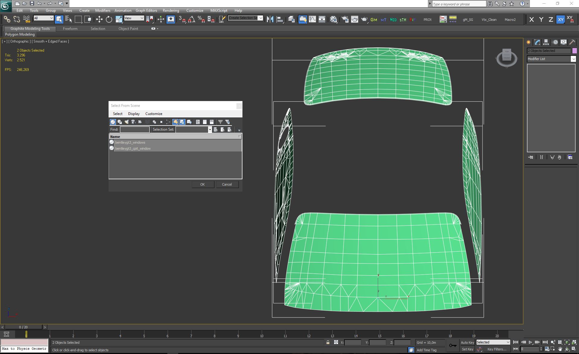
Select both both the Exterior and Interior mesh. Hide any polygons which is not mapped with the Windscreen shaders;
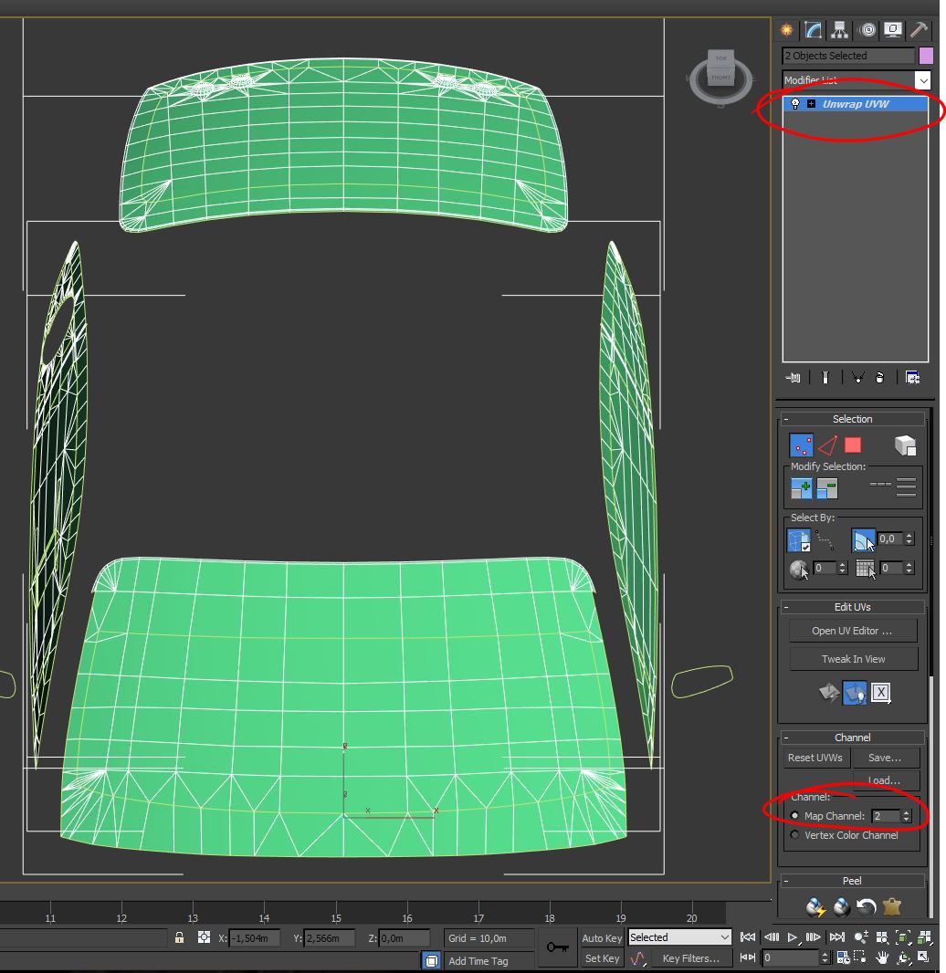
With both mesh selected, add a Unrwap UVW modifier on top of the stack. Select the Map Channel to 2. Click either Move or Abandone on the dialog box (doesn't matter since we have to remap that channel);
For the main Windscreen (in and out), sometimes would be better to Peel the Geometry, to limit the distorion. You can then use Box Mapping to produce all the remaining cubic projections, and place the different glass islands respecting the Canvas TOP/BOTTOM areas, as explained above. Since the rain map it's tilable, you don't need to overlap islands on the bottom part.
Once you used the Box Mapping, be 100% sure that your {left windows (both internal and external) are mapped in the UV, with the front pointing left} (as in the UV map in the picture), and the {right windows (both int and ext) are mapped in the UV, with the front pointing right} (as in the UV map in the picture). This should be pretty much what Box Mapping do, if your car model is using correct coordinates, but better to check before to push your changes;
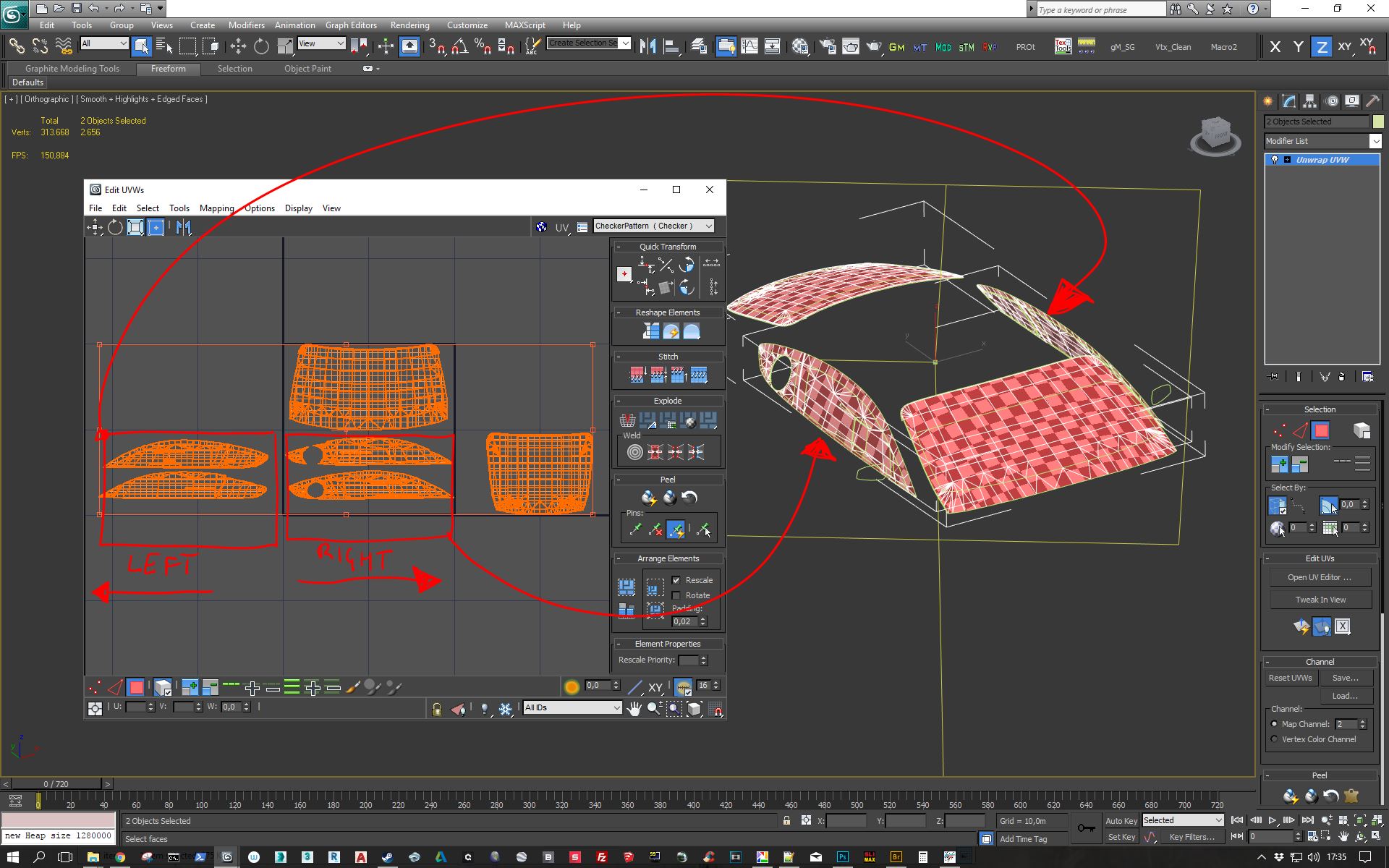
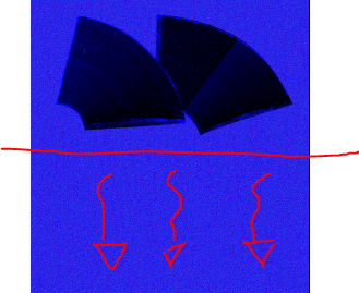
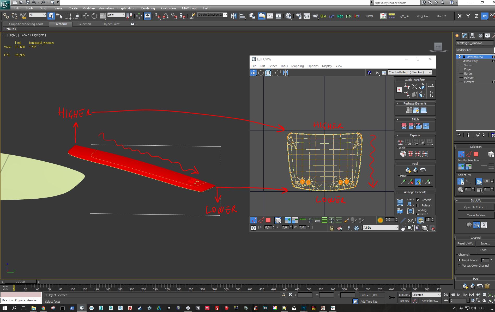
IMPORTANT; Be sure your back window (if present) is mapped in the canvas with the lower part of the glass facing down, and the higher part facing up. This is to force rain drops to roll down, from top to bottom, when the car is not in motion. See the picture:
At this stage be sure you are keeping a constant scale between islands, and fine tune the mapping using the CheckerPattern as a guide (see picture above). Mapping is now done.
2.3B (ADDENDUM) - Windscreen and Vertex Illumination Painting
A problem to solve, to make the final effect more realistic, it's to tell our RainFX code, where our windows are positioned around the car, so that we can render the streaks effects, building up and rolling in the correct position.
We'll be using the Vertex Illumination RGB vertices color, to paint those windows using that mandatory convention:
- BLACK (0,0,0); FRONT WINDSCREEN
- RED (255,0,0) ; BACK WINDOW
- GREEN (0,255,0); LEFT WINDOWS
- BLUE (0,0,255) ; RIGHT WINDOWS
Before proceeding with paint let's select the windows mesh, internal and external, and set both mesh to show up the Vertex Illumination Color visible on our viewports. Be sure your viewport is set to "Smooth+Highlight". ;
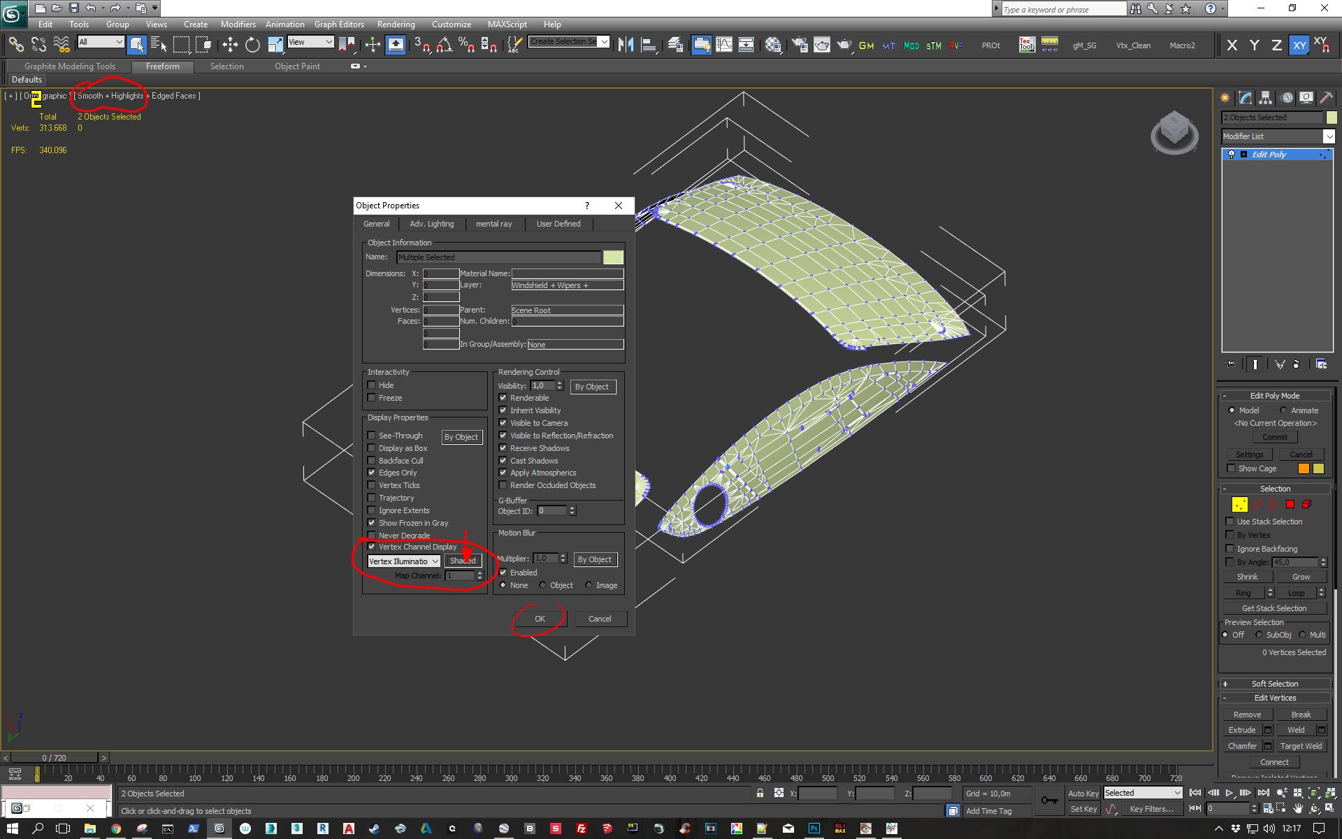
Now the mesh are showing up the V.I. color on the viewport. This will help us to understand if we are doing right.
The task now is very easy and quick. You have just to select both external and internal windows meshes, and add a Vertex Painter to the stack;
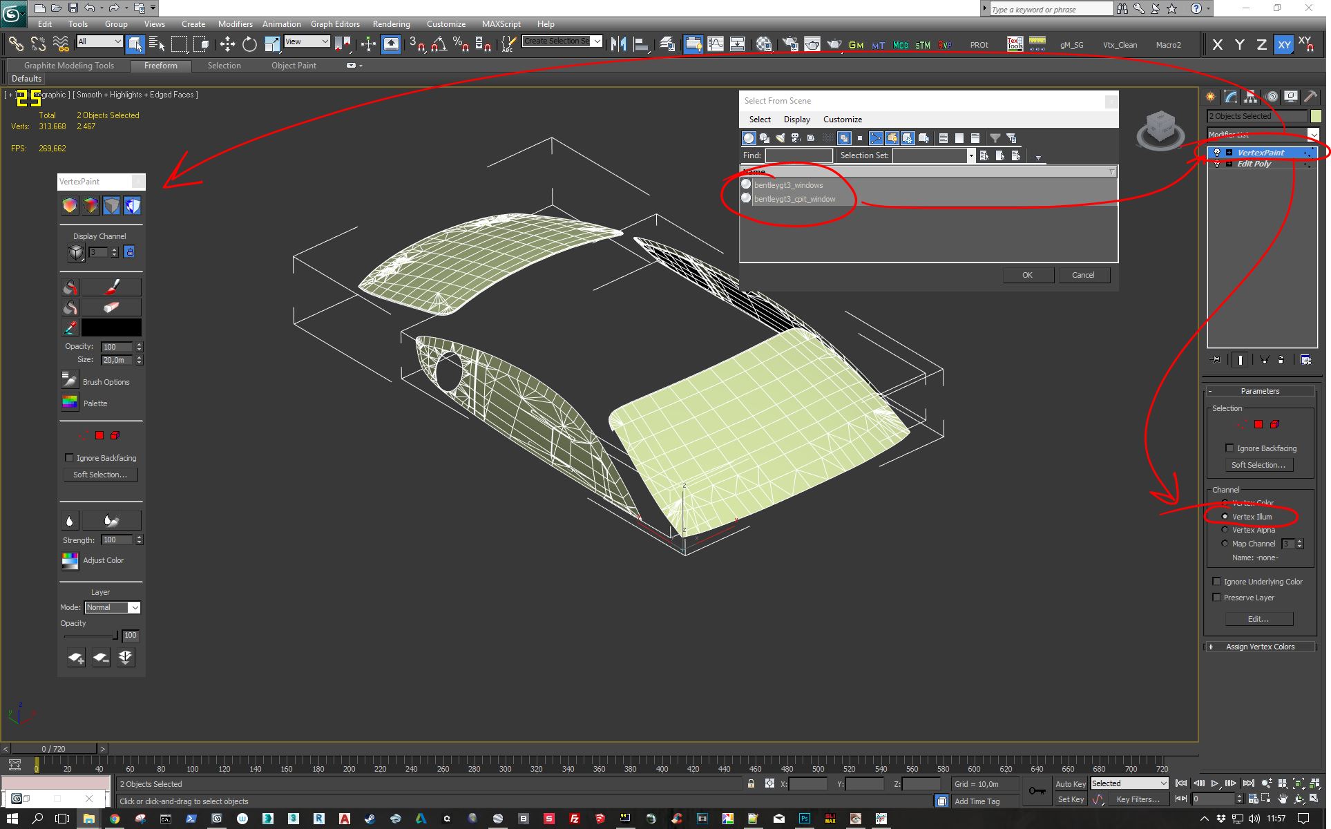
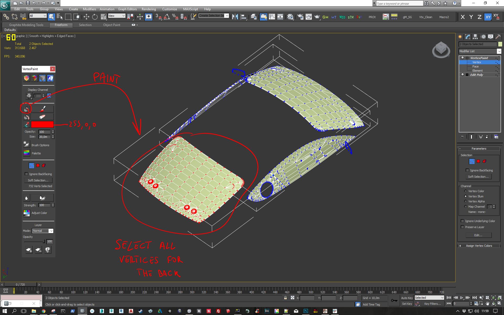
Now that you have the stack ready, and you set the Channel to work at Vertex Illumination level, you can enter the Vertex Painter modifier, and in vertex mode let's select all the vertices for the back window. Remember, if you have internal and external mesh for that, select vertices for both. Same for all other windows.
Once you selected all vertices for the back window, you can set the RED color (255,0,0) in the Painter modifier (see the picture), and then you can just fill those vertex with color, using the color bucket;
Now you should get this;
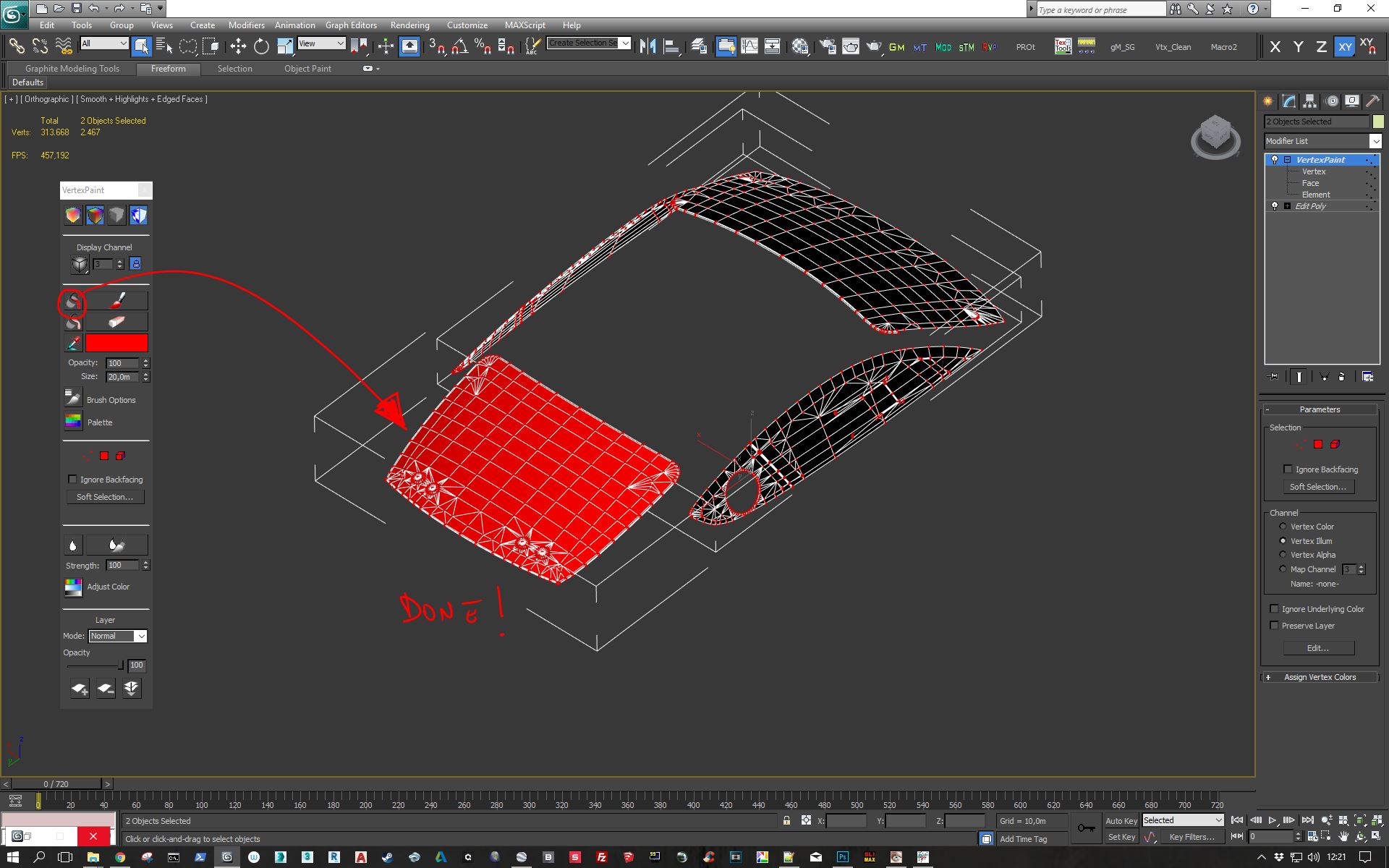
Now, after Red for the Back, you have just to repeat the procedure (you can re-use the same Vertex Paint in the stack), and paint the remaining windows. Black for the Front, Green for the Left, Blue for the Right. After this task you should have this;
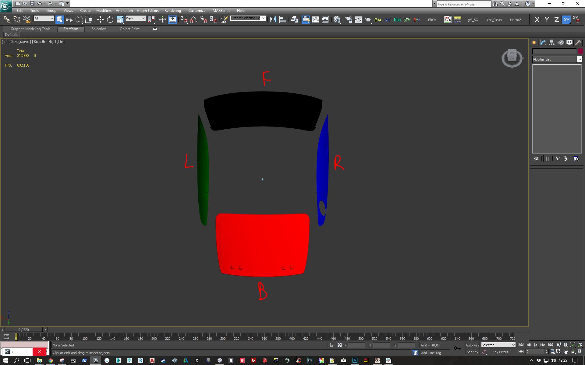
Task is done!
2.3C - FRONTAL Windscreen UVW template creation
Before moving to the next task, we need a UVW template (4096*4096) showing the main windscreen (in and out) in the canvas. This is important as it's our main reference for the art creation.
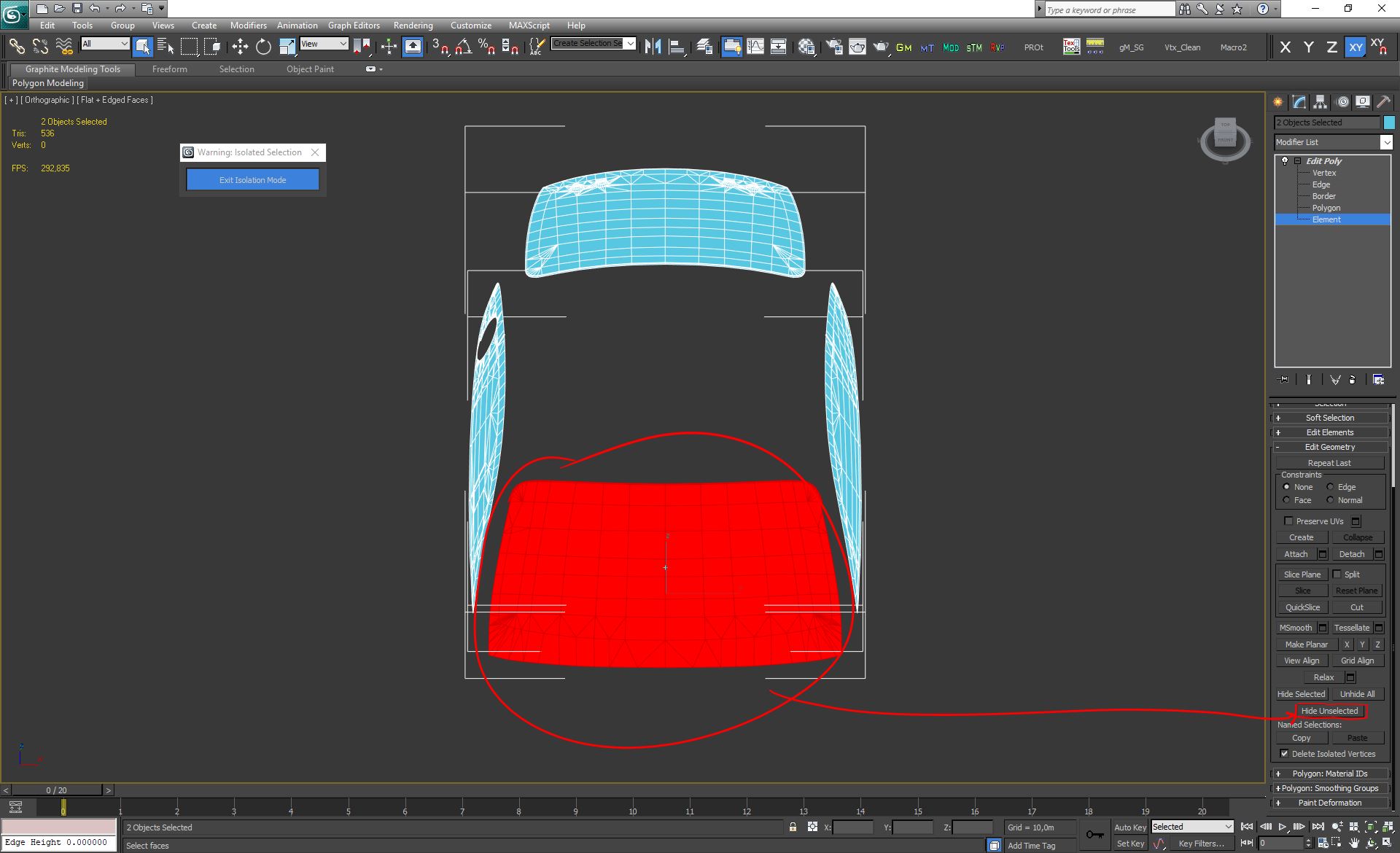
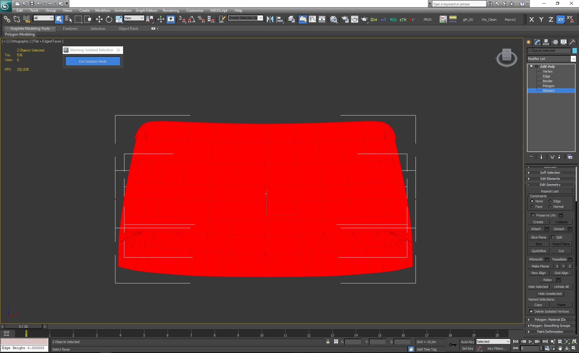
To do so you can collapse the stack, and still with both mesh selected, add a Edit Poly modifier on top of the stack. Now go down to Polygon/Element level, and select both Windscreen In and Out Elements. At this point, in the Editor Geometry Rollout, you can press Hide Unselected to hide everything else but the Windscreens;
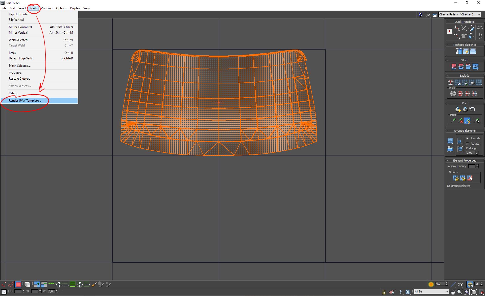
To render the UVW Template we need to add a new Unrwap Modifier on top of the stack, select the Map Channel to 2, and click on Abandone to the UV move request (since we want to retain the mapping we just did). In the UVW editor click on Tools and Render UVW Template;
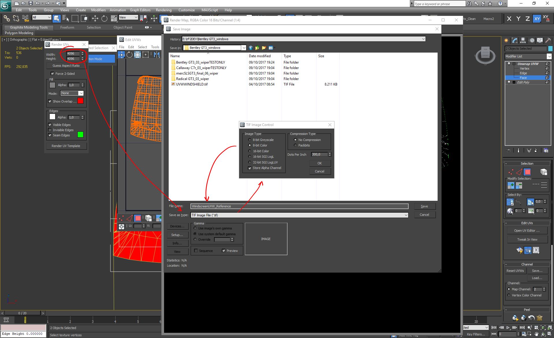
Set the RENDER UVs to 4096*4096 (we will work @ 2048 on the rain art textures, but better to always render 4K for better wire downsample), click on "Render UV Template" and save as TIF;
Now we have everything we need from the UVWs, and mapping is also complete, so we can move to the next Task.
2.4 - Create a visual projection reference of the wiper animation
This is a delicate task, as much of the final quality of the effect depends on how we are translating the Wiper arc animation on the windscreen, to a static Arc map, which is describing such motion through a shape (mask) and a color gradient (motion).
To help this process we will be using a little trick so that we port all the animation wiper frames, into a single image. We'll be using this image to create the Arc. These are the steps to achieve such reference image;
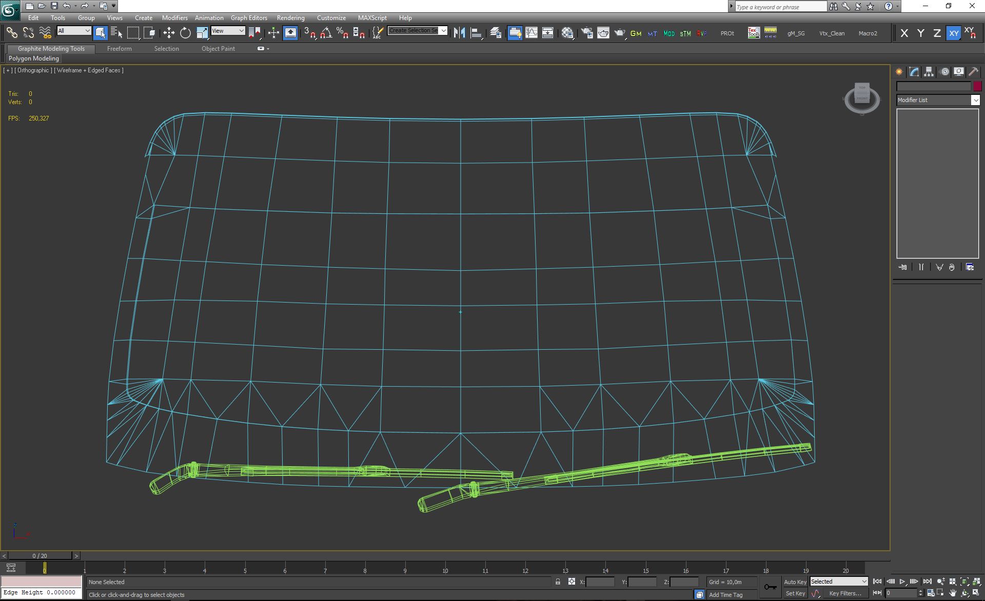
Unhide the Wipers (we don't need the bones to be visible, just the wiper mesh);
Create a Target Camera and setup as the following picture. Be sure to check the Orthographic Projection to avoid any distortion due the FOV;
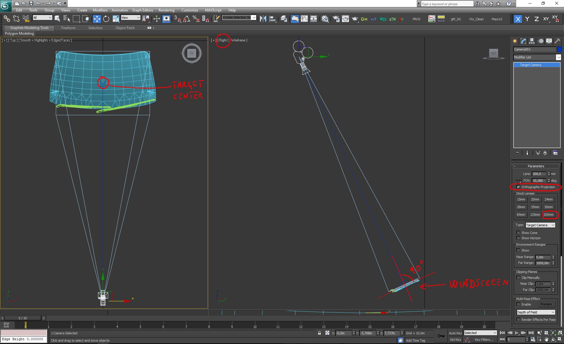
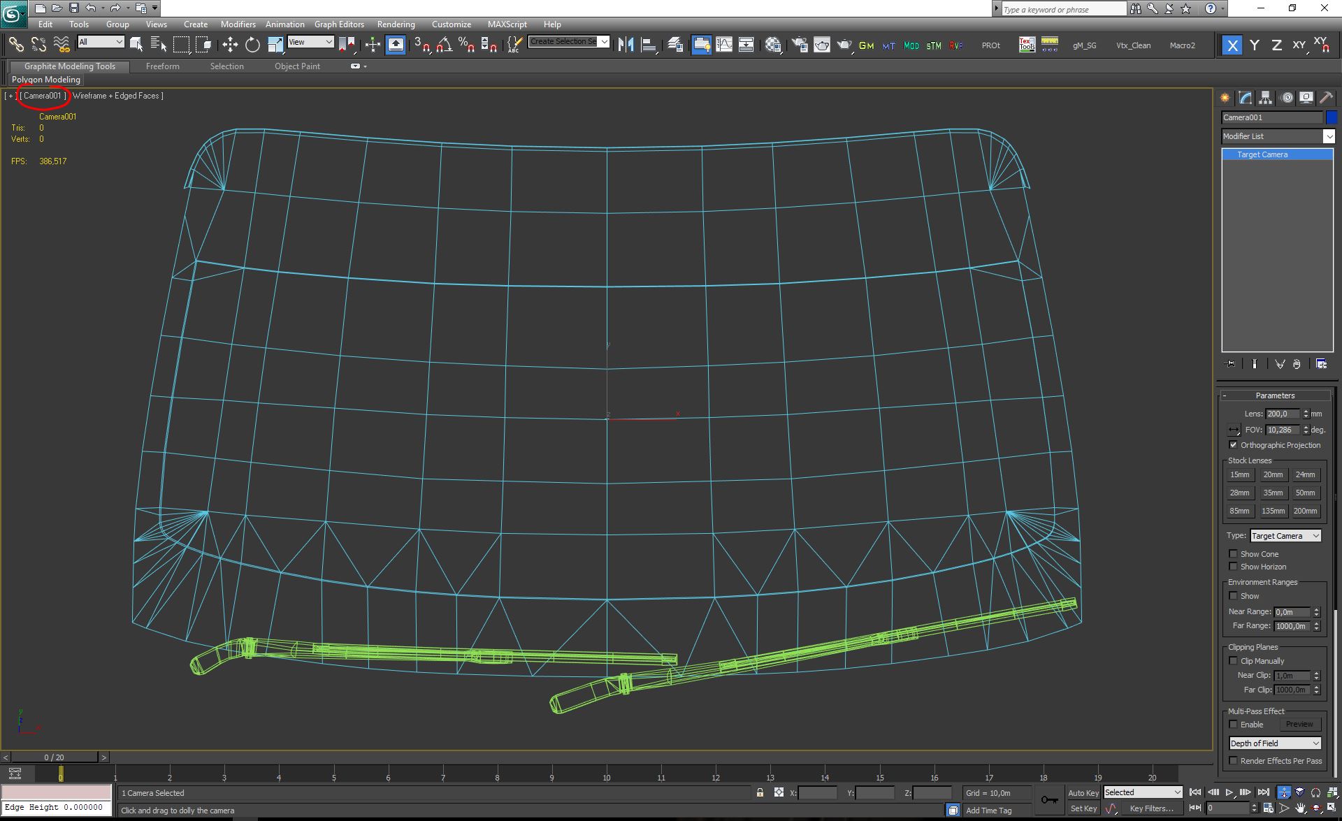
Load that Target Camera in the Viewport and fine tune the distance from the target, to maximize the windscreen view, without cutting any part of it;
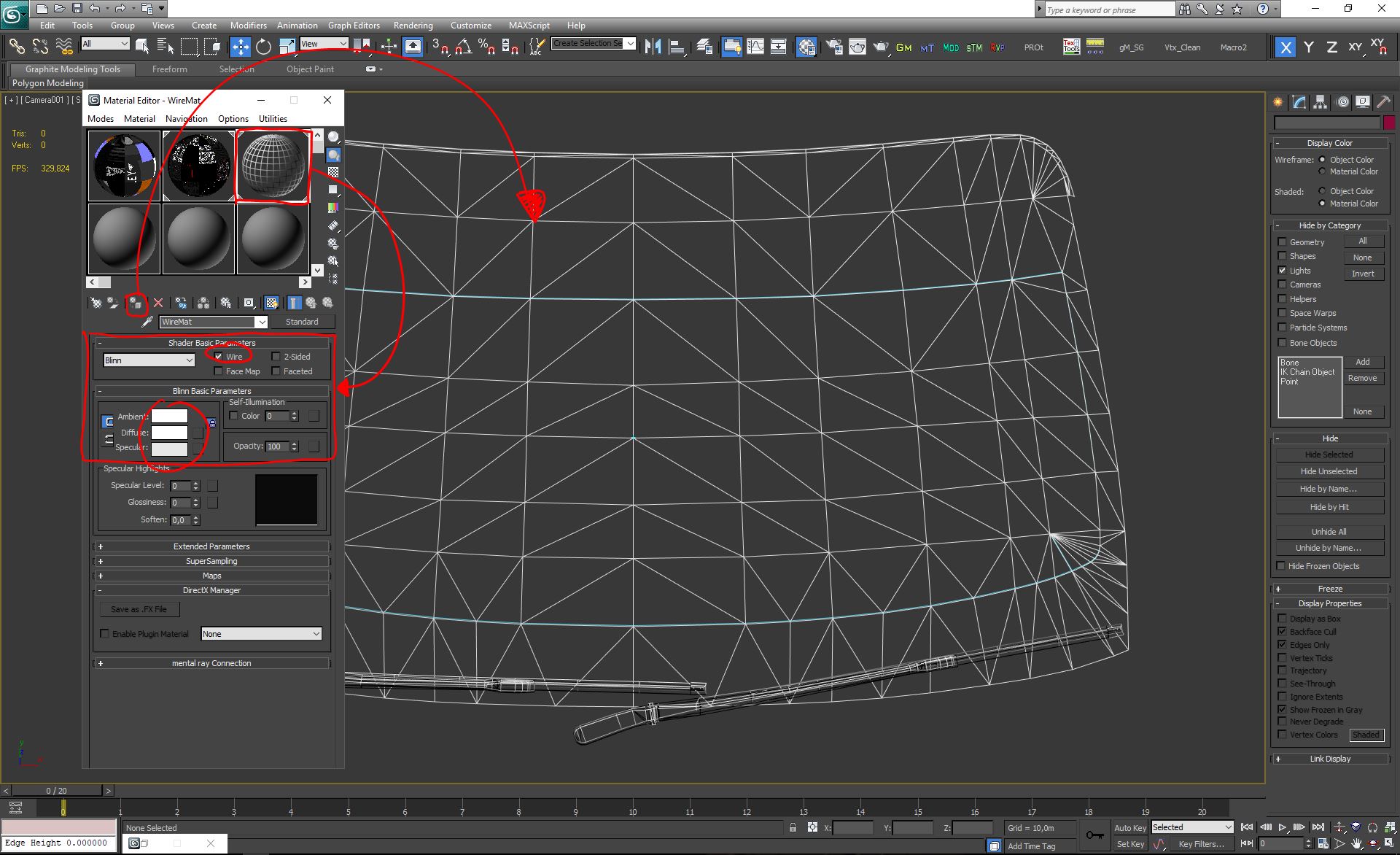
Create a Wire Material, setup as the picture, and apply to the selected mesh (windscreen in and out);
Setup the Render as the following picture. Be sure to setup a file format and a destination folder for your animation files (.JPG is good enough). When you are ready you can press Render and wait for the process to complete;
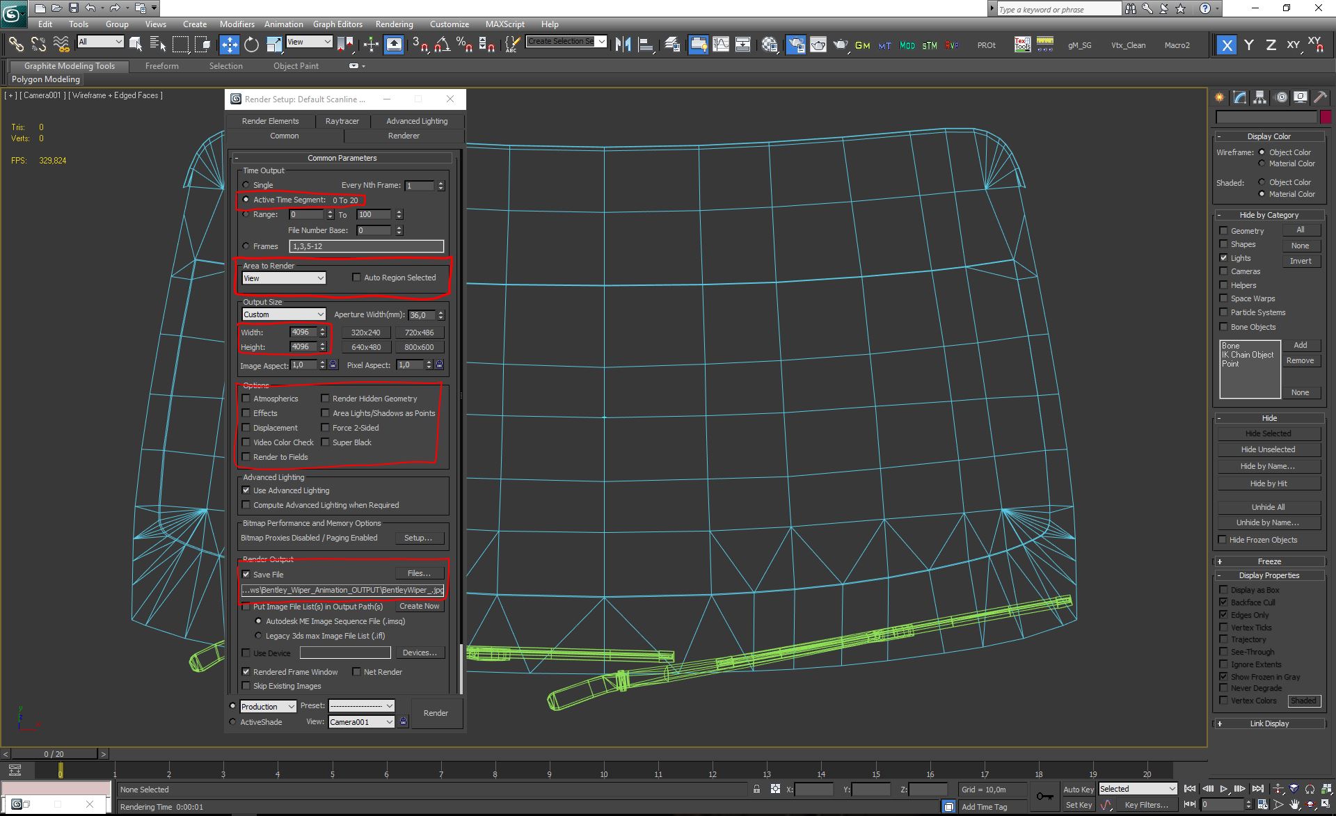
At this point you should have all the animation files in the folder you've setup in the Render Output;
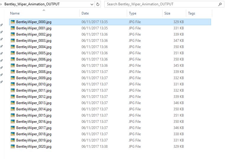
Now that we have all the animations file, we can save all the projects and move to Photoshop, with the next Task.
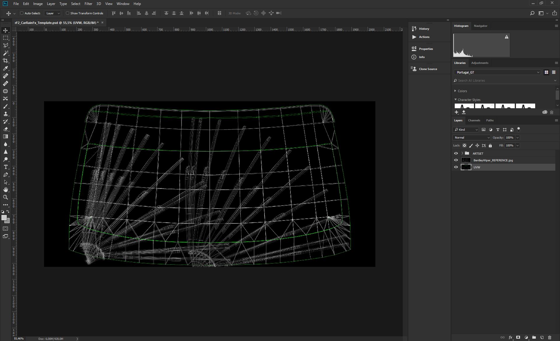
2.5 - Create Wiper/s Animation Reference Image
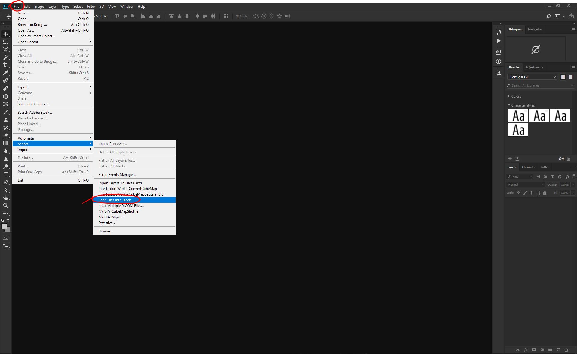
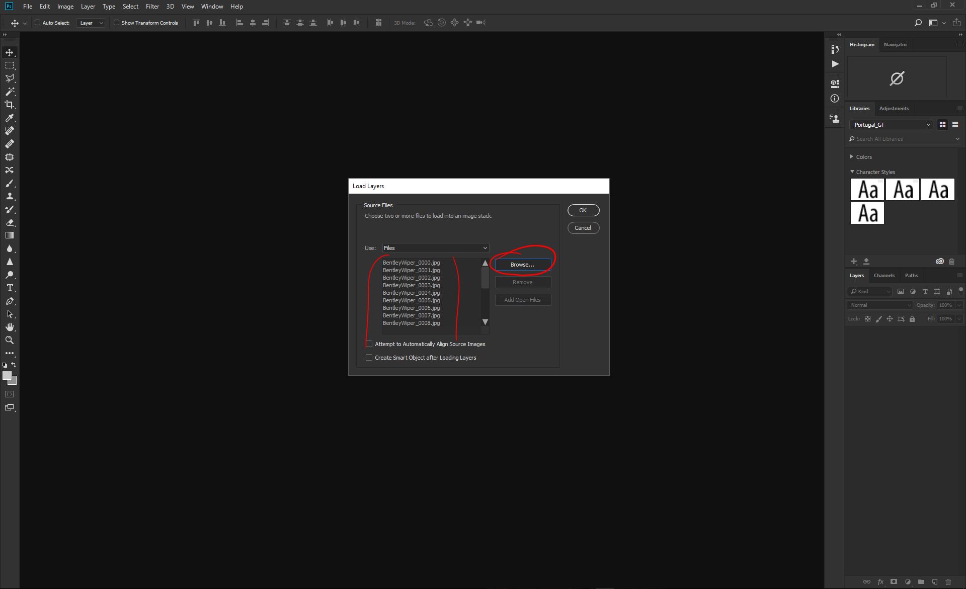
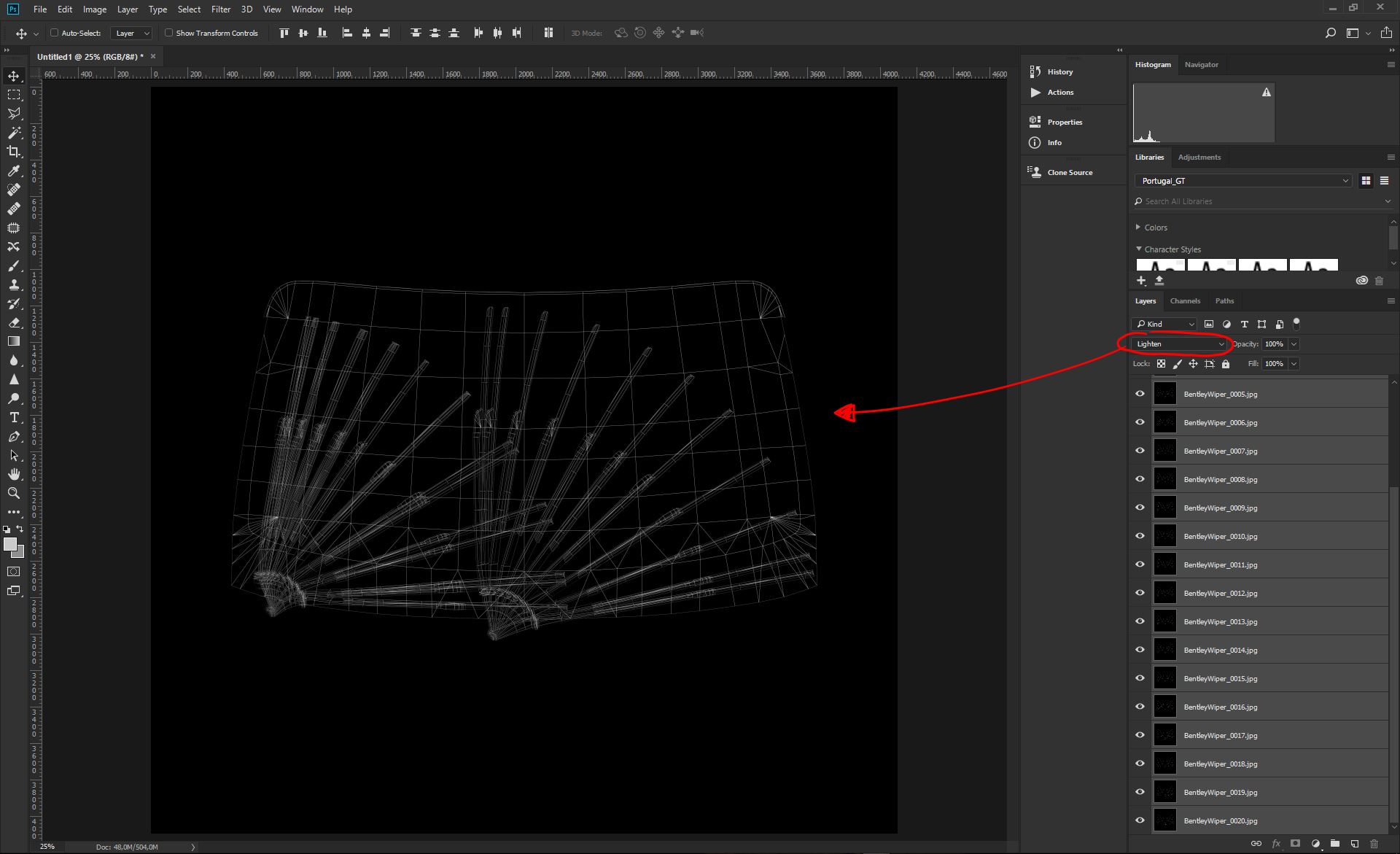
Open Photoshop CC and let's import all the animation files in a stack;
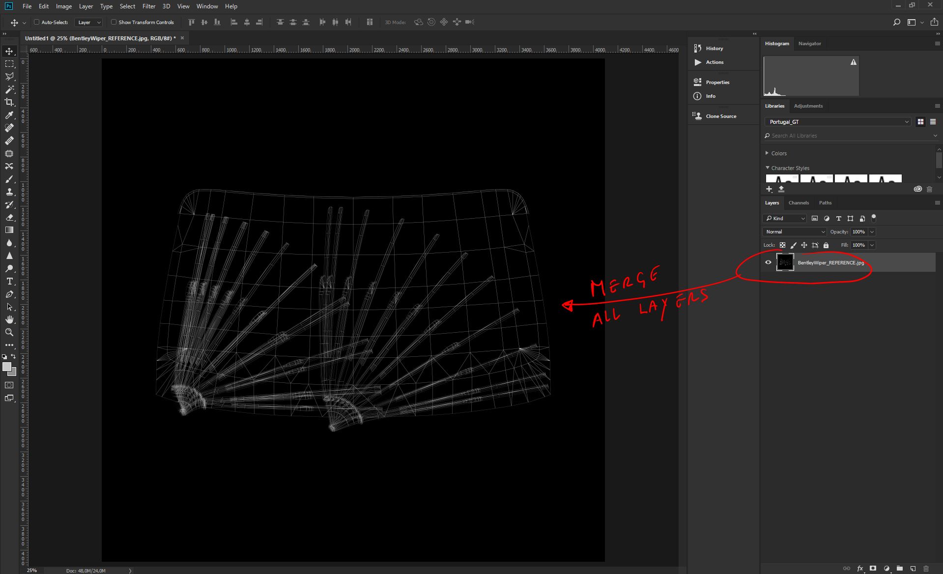
Select all the Layers and Set the blending to Lighten, then merge all the layers into a single one. That is your Arc Reference Layer;
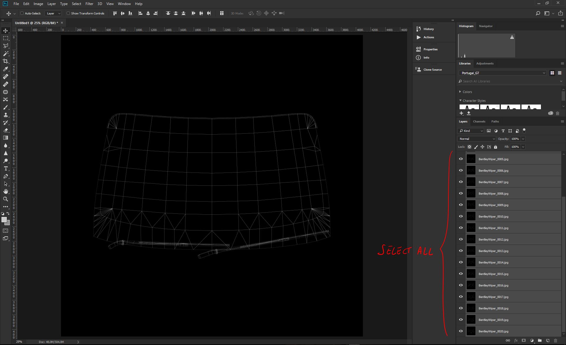
Merge all layers and save the image as BentleyWiper_REFERENCE.jpg
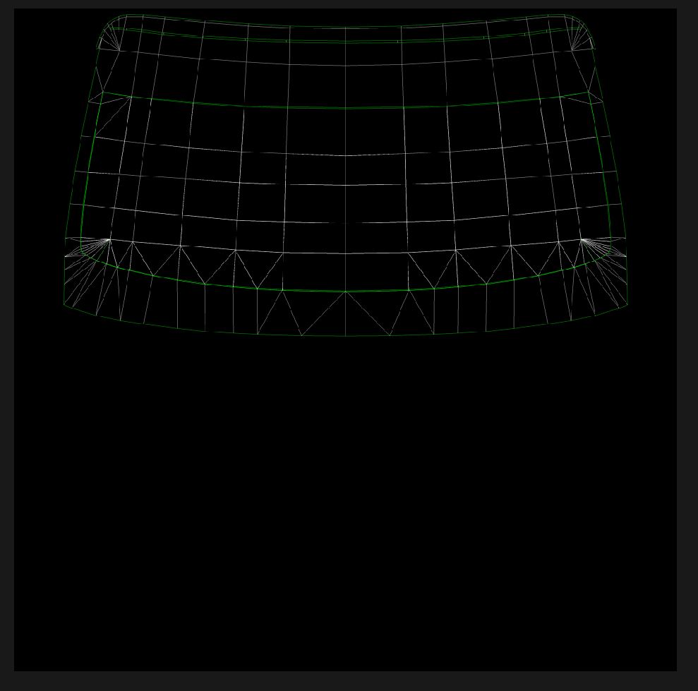
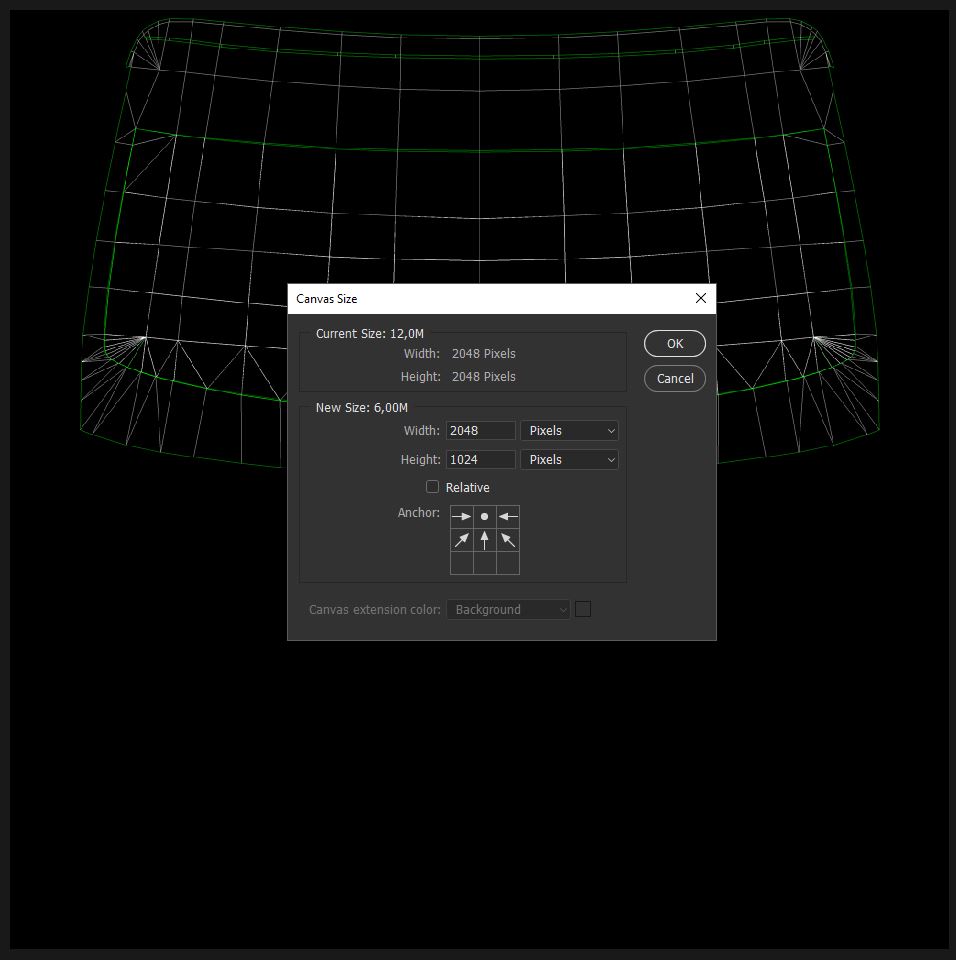
Now we can open the UVW template we did early in the process and rescale to 2048*2048, since our target is a canvas of 2048*1024;
Now we can place in the stack, the BentleyWiper_REFERENCE.jpg, on top of the UVW template, and set that Layer to Lighten blending. Resize that last image to match, as much as possible, the UVW template underneath;
We now have the base reference ready to build up our Art Set and move to the next Task.
2.6 - Create Wiper/s Arc Masks
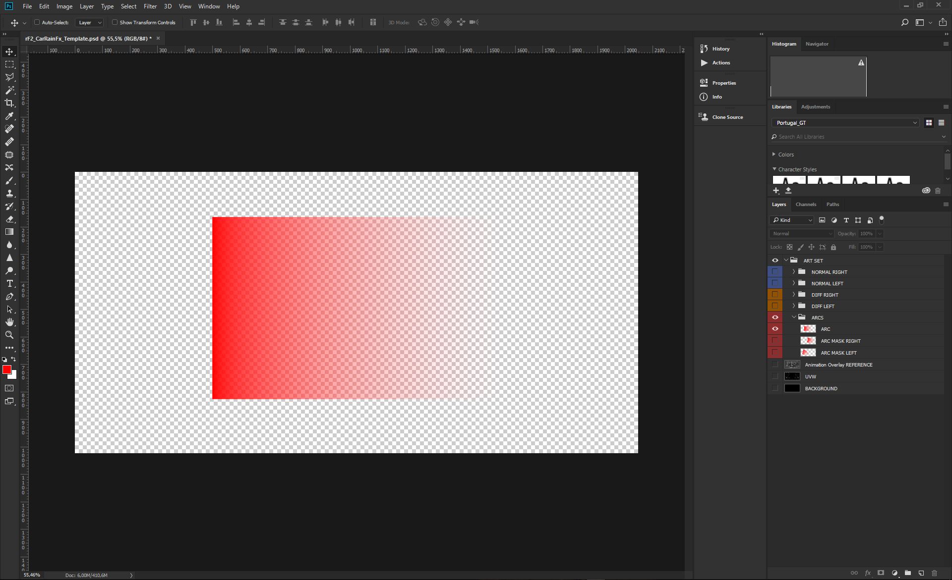
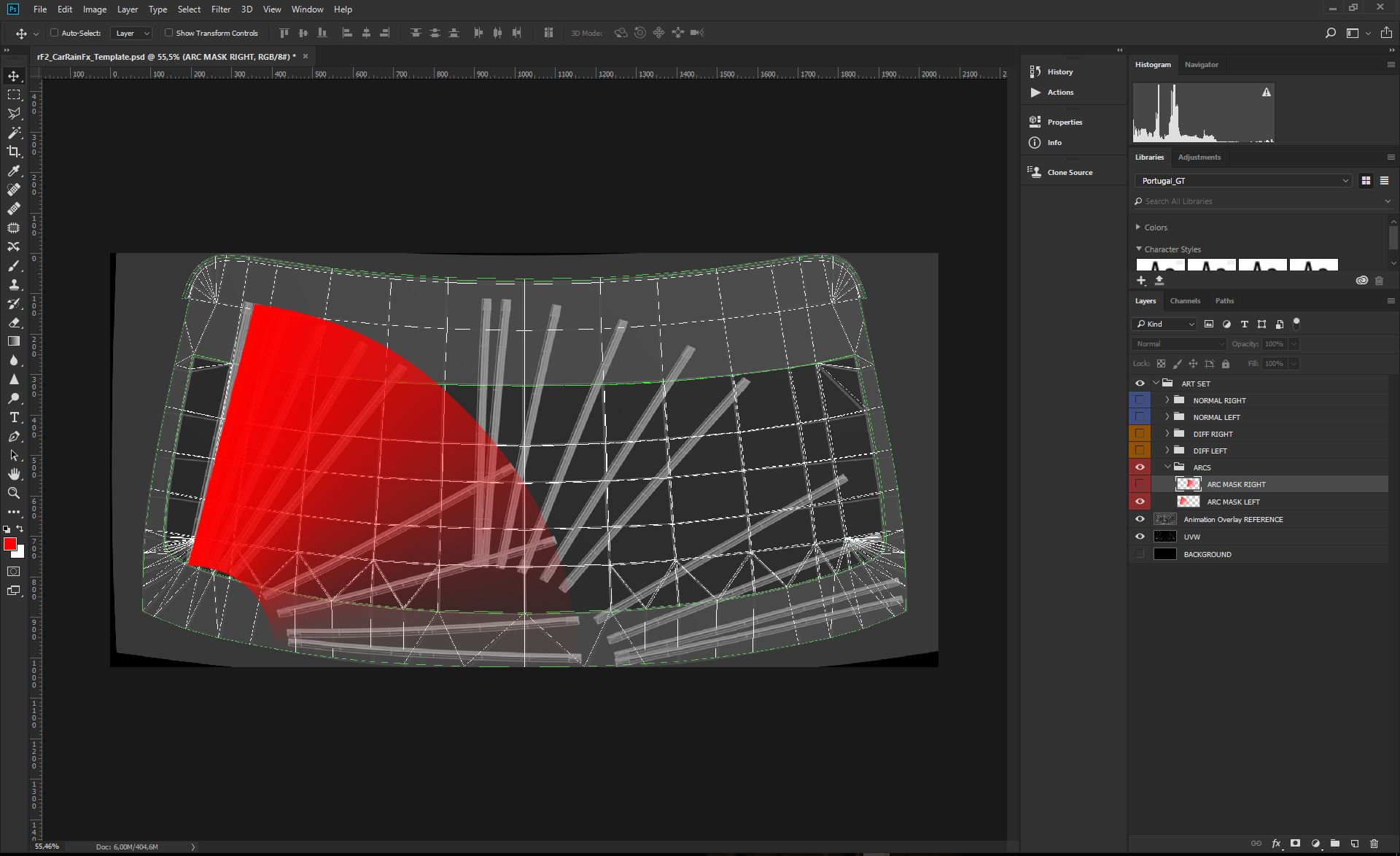
We can start creating an easy rectangular gradient, from full RED (255,0,0) to full Transparent. Create a Rectangle long enough to be shaped into the wanted Arc mask. IMPORTANT; If you have a wiper that does go side to side, but starts from the middle on the windscreen, the gradient always must be from side to side, describing the entire arc on the windscreen, with the full transparency on a side, and full red on the other side. Never use a symmetric gradient, with the full transparency in the middle. If you have single wiper system, that does Start&Park in the middle of the windscreen, you will still want an arc gradient from down to down (like for any other wiper system), and then you'll force the mask to start at 50%, through the use of the key points (we'll see these later in the guideline);
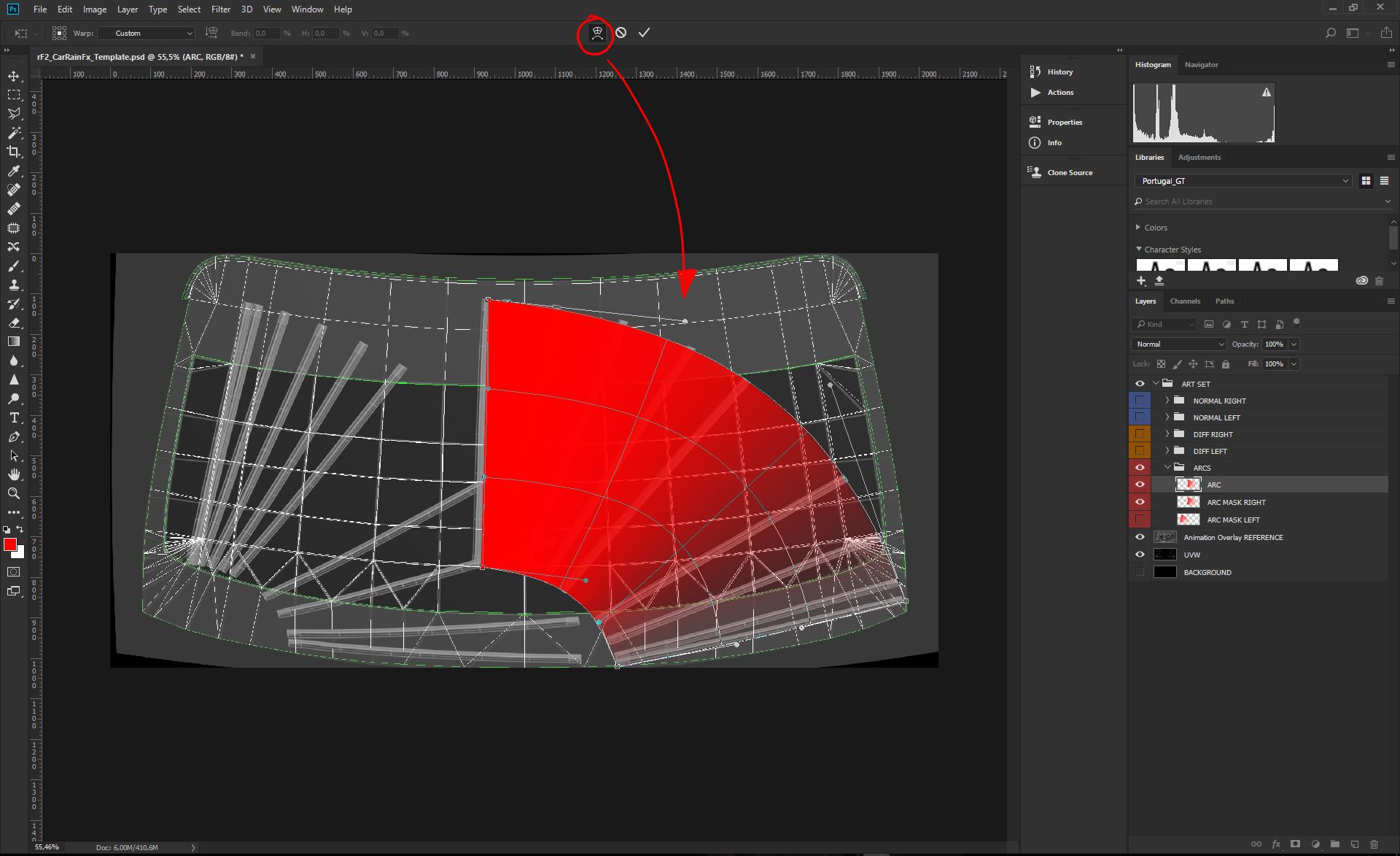
Press CTRL+T to enter the Transform mode, and then press the Warp icon to access the arc deformation. Goal here is to shape the Gradient to match the wiper animation, as much as possible, keeping and saving the gradient integrity. This is achieved setting the deformation grid inside the arc to producing clean quadrants, with 90° intersections, as in the picture. When your arc does look good enough, press Enter to apply the transformation;
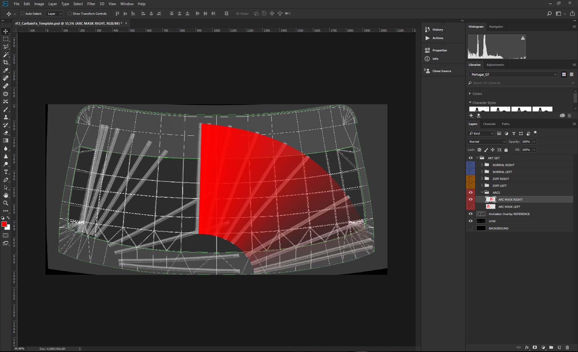
Proceed same way for the Left Arc;
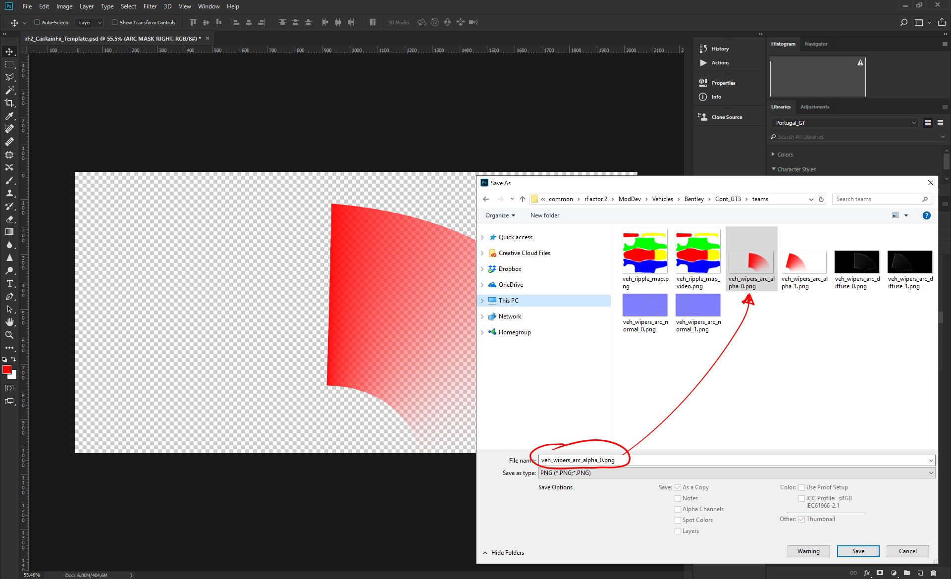
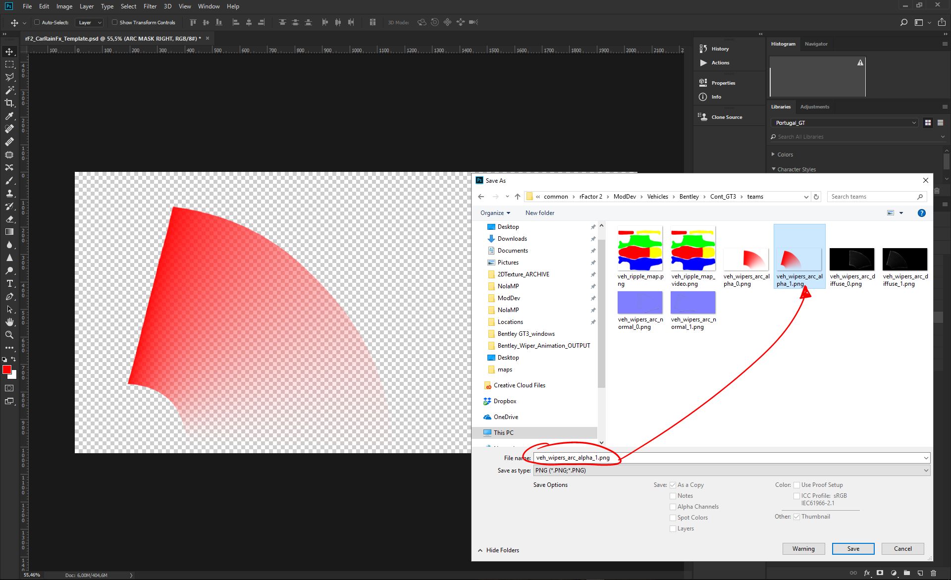
Now you have both Right and Left Arc Mask, ready to be saved for the game engine. We need a .PNG format, default settings, saved with its own transparency. Both Arcs needs to be saved into the "teams" folder, of the car mod you are working on;
Name for the files are;
- RIGHT ARC; veh_wipers_arc_alpha_0.png
- LEFT ARC; veh_wipers_arc_alpha_1.png
PS: if you have just a single wiper system, you save just as "veh_wipers_arc_alpha_0.png"
2.7 - Create Rain Buildup Diffuse Map/s
Before to start we need to remember that all these events in the Diffuse, they all need to stay INSIDE the Arc Masks. Every pixel outside that area will be dropped.
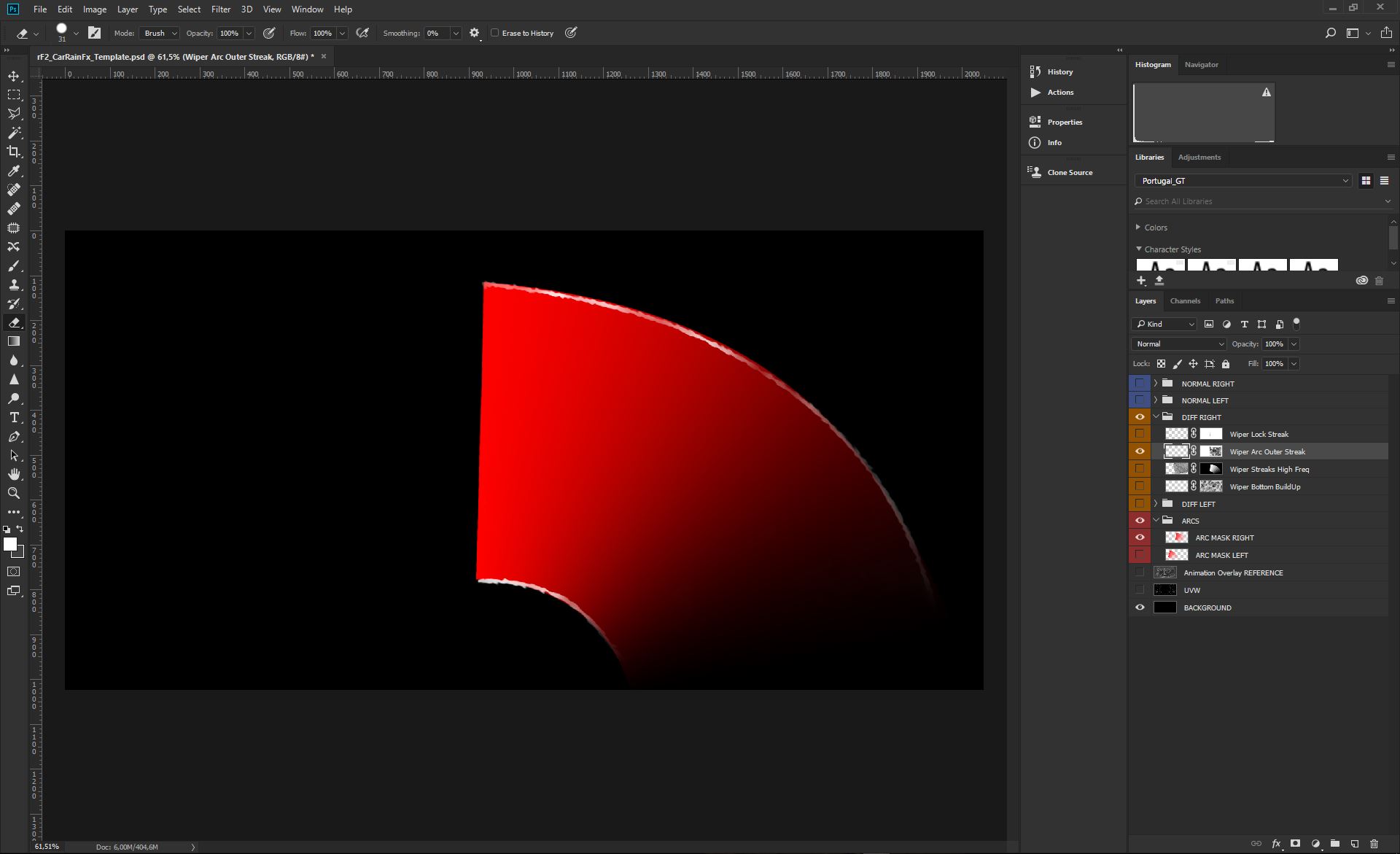
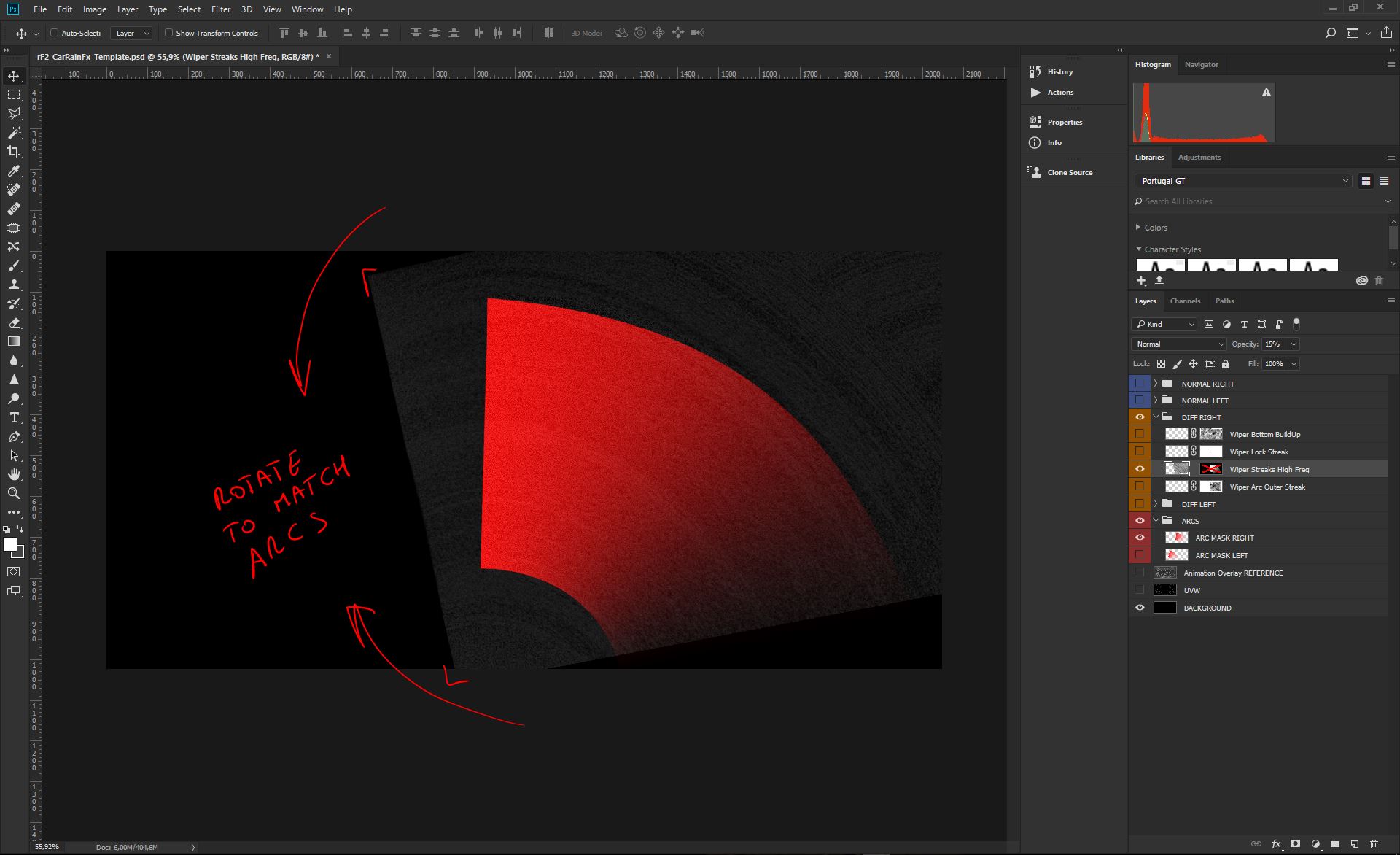
Using a set of Water Effect in the template, we start building the Wiper Lock Streak, that happens when the Wiper does reach its max position in the arc, before bouncing back to the bottom position. The element it's not all 100% white, but has many variations that will be useful for the randomness we were talking about early in the document. This element is part of the Template, so you don't have to recreate it. You can just scale and position the Template element to match your car Arcs. These are the 2 main diffuse elements you have in the template;
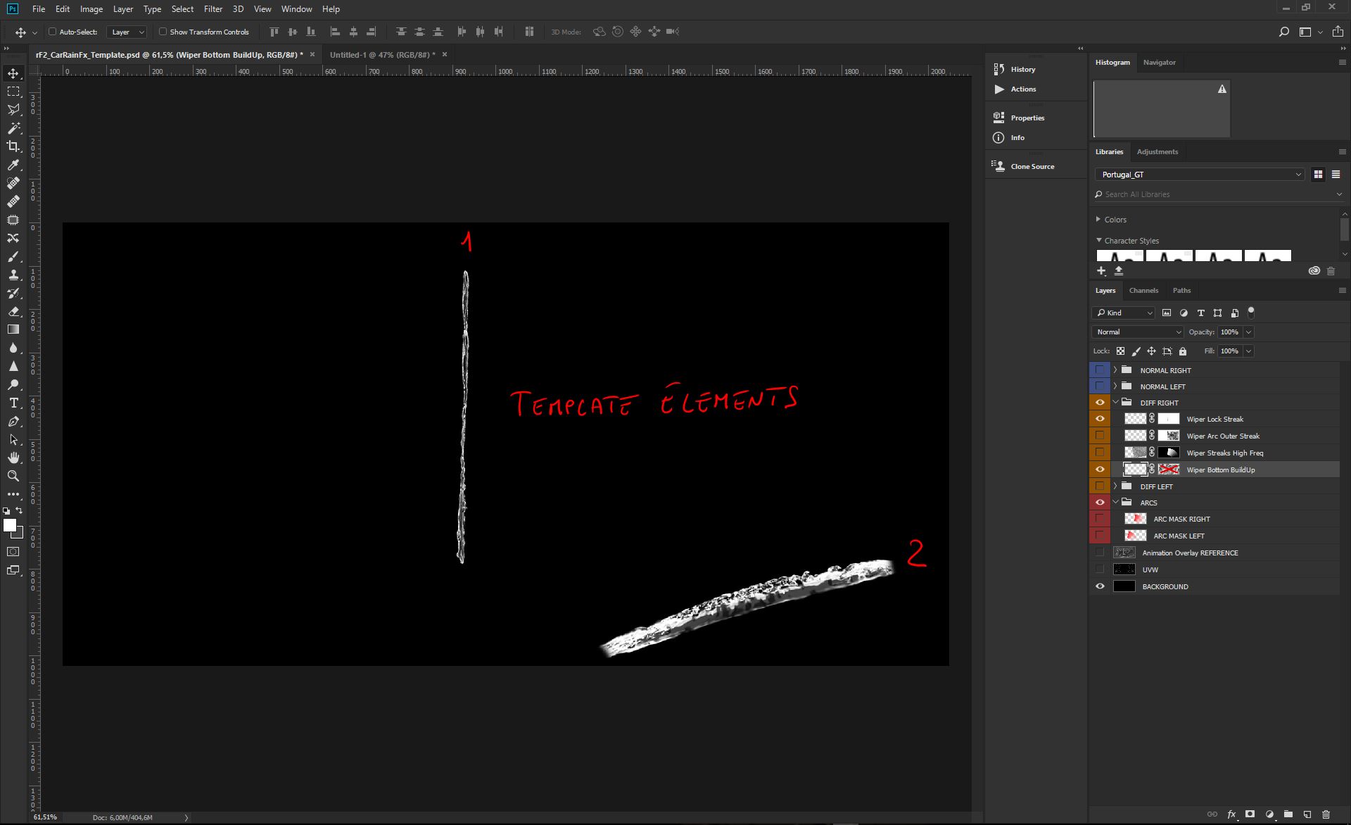
All we have to do at this stage is find the proper position/size for the first Template element, to match the top "lock" part of the Arc mask. Remember the element has to stay inside the mask;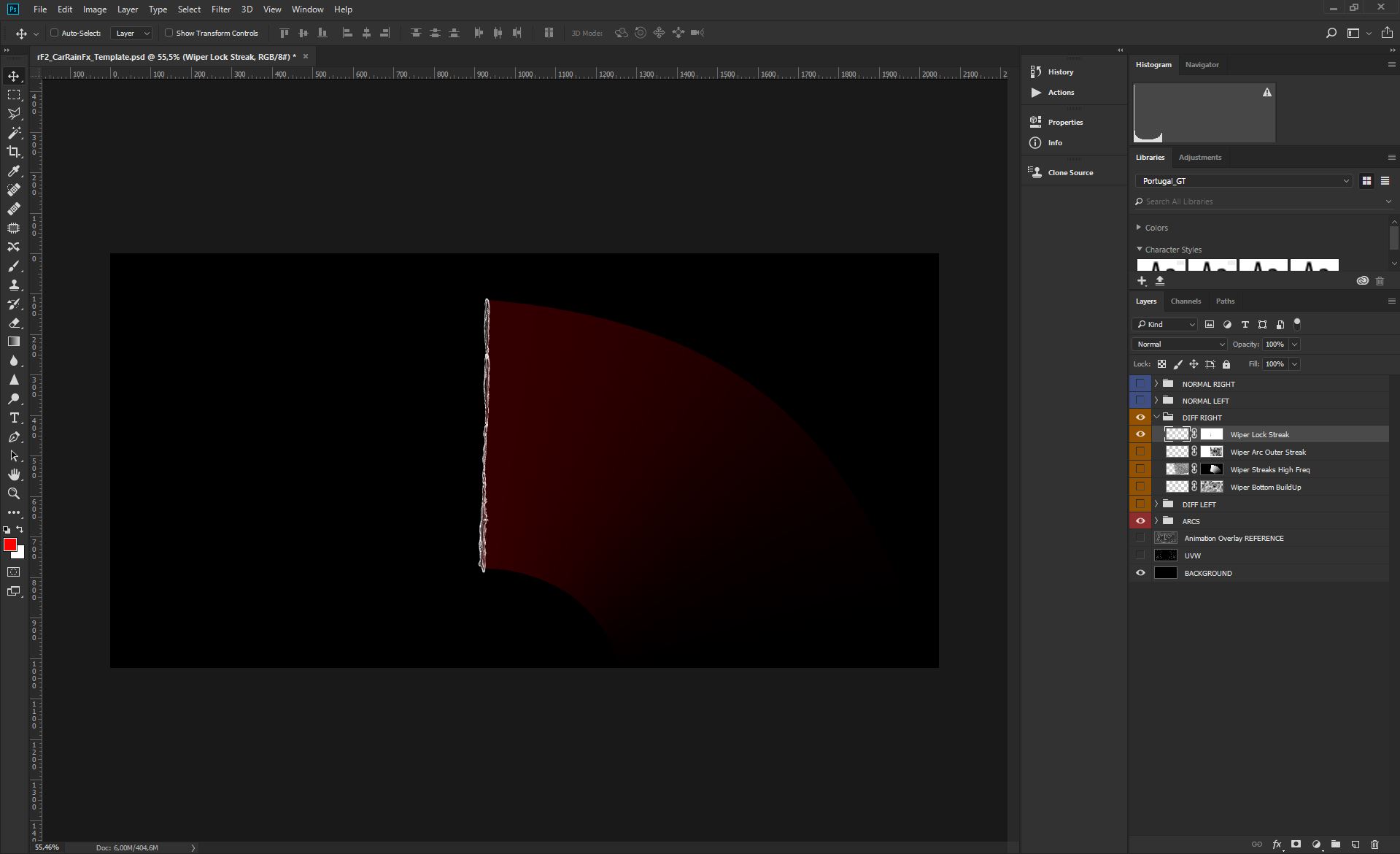
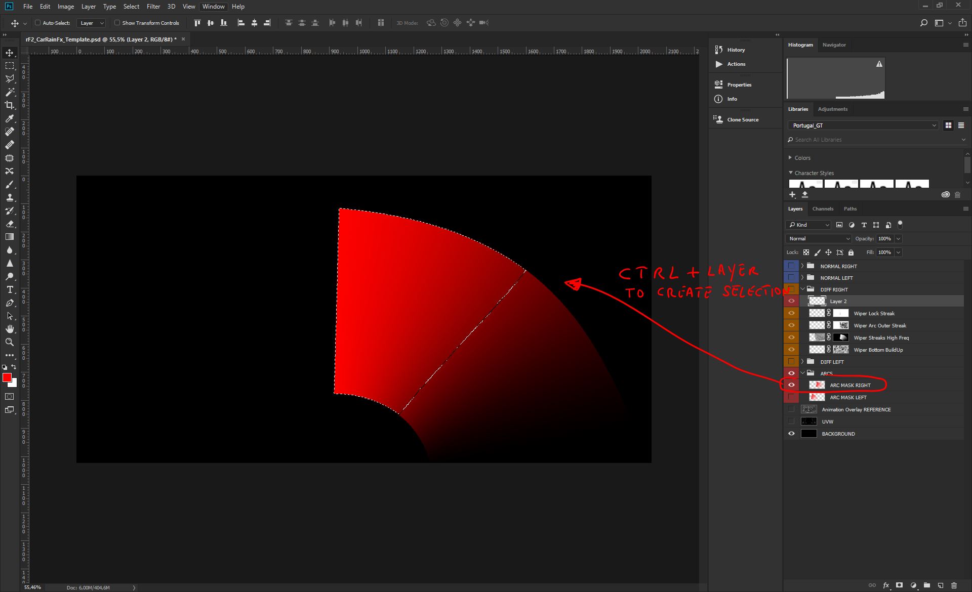
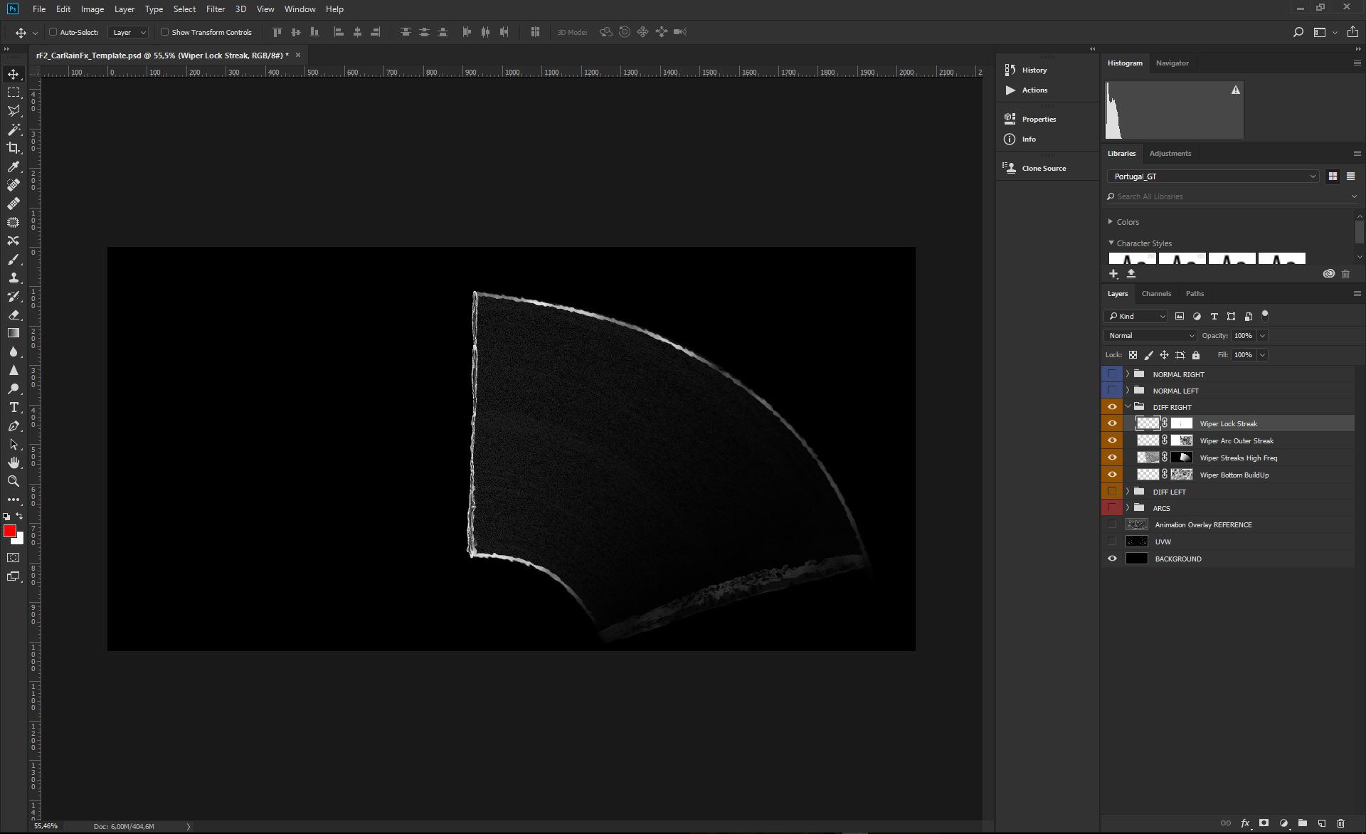
Now that we have the first element in place, we want to create the water accumulation outlining the Arc Mask (still they need to be INSIDE it to be rendered).
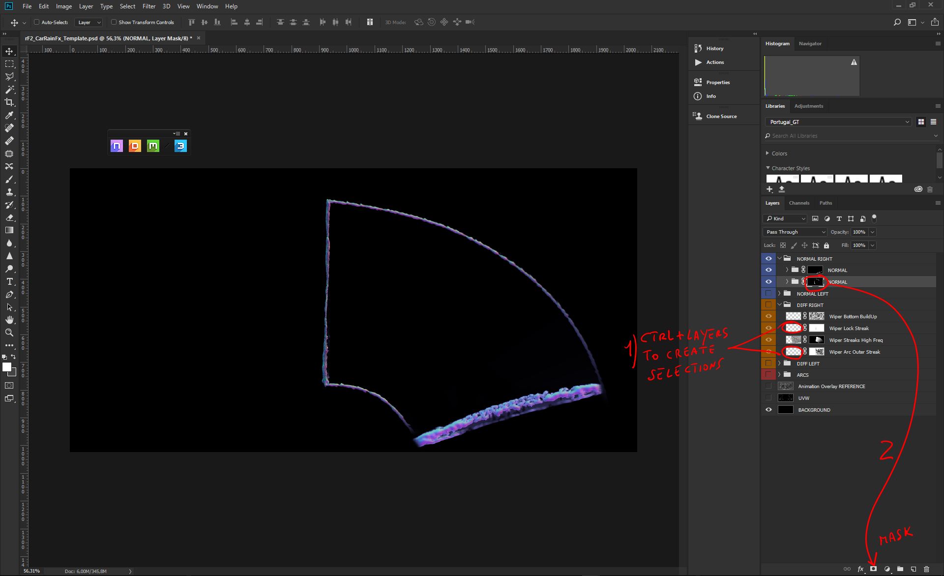
Press CONTROL while clicking on the Arc layer. This will create a Selection. Create a new Layer and Select it;
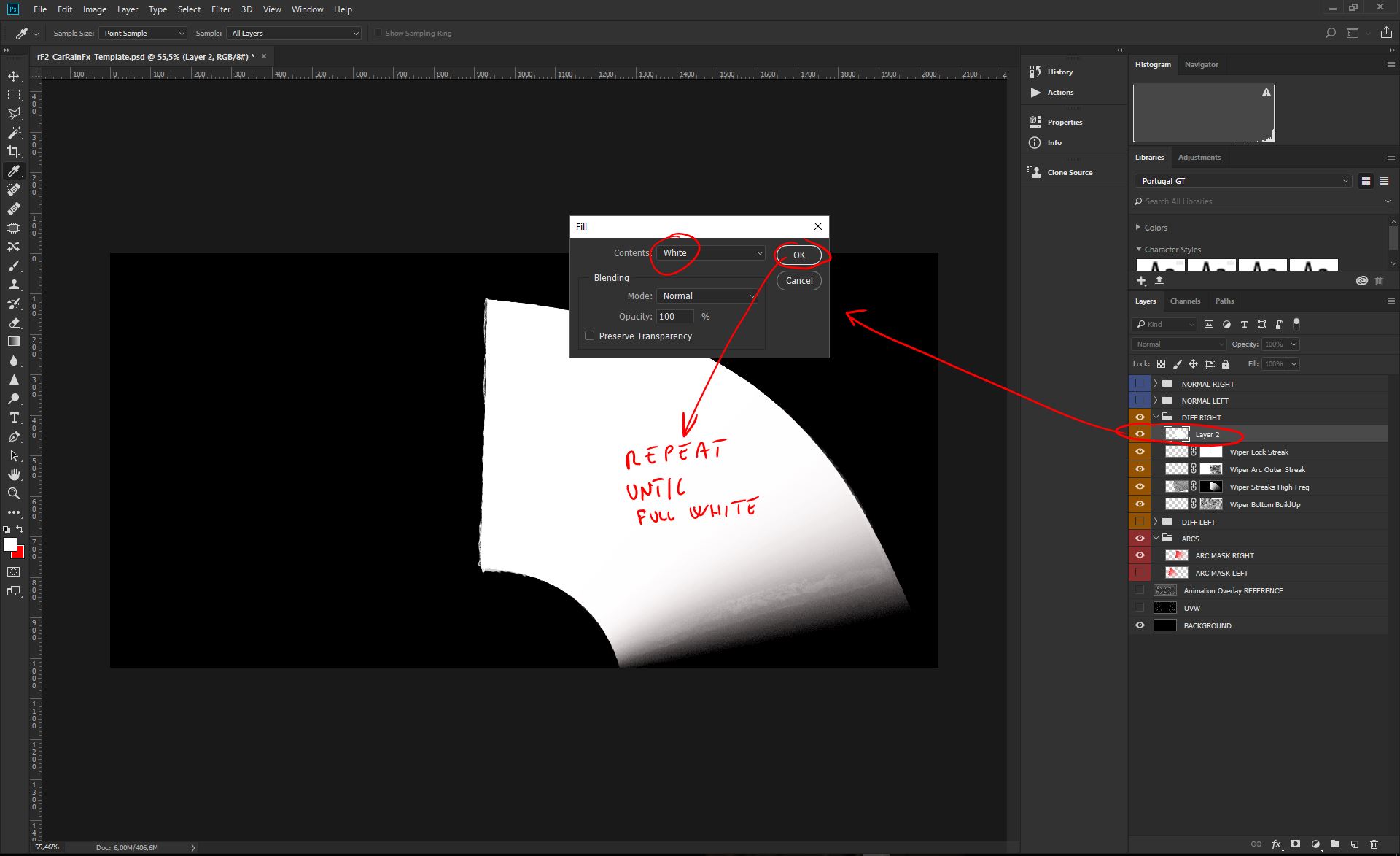
Now, with the new Layer selected, and the Selection active, press SHIFT+BACKSPACE to Fill with White Color. Since the selection is a gradient mask, keep repeating the process until you have a good solid white, with a bit of gradient at the bottom of the arc;
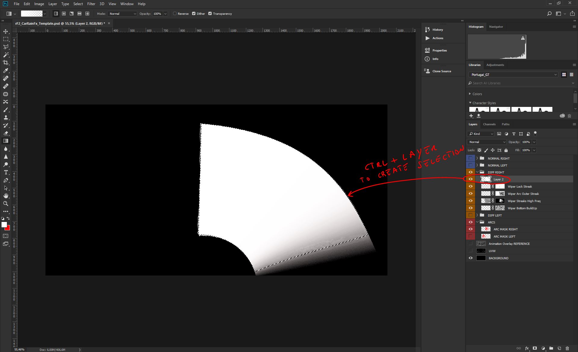
Now press CONTROL, while clicking on the new Layer, to create a new Selection;
With the active Selection, go to Select--->Modify---->Contract;
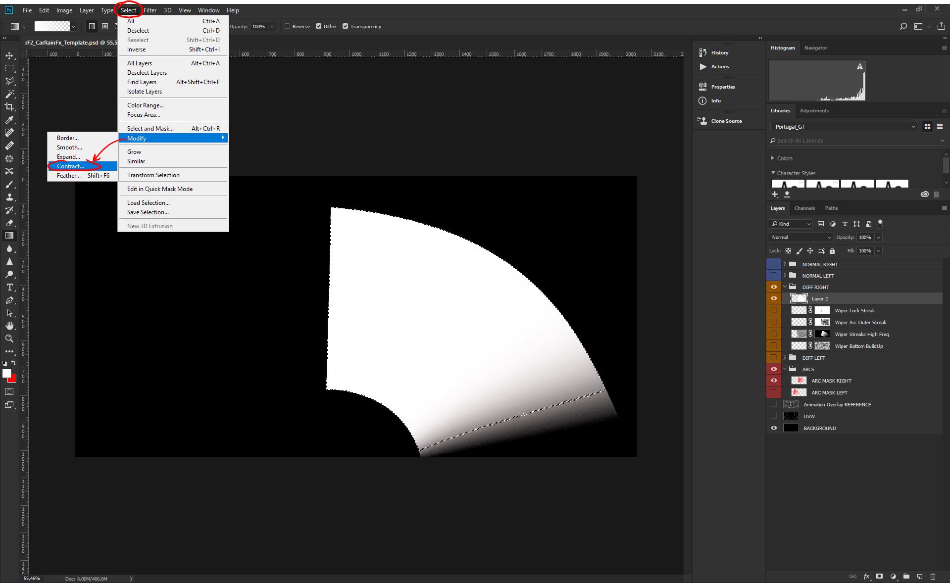
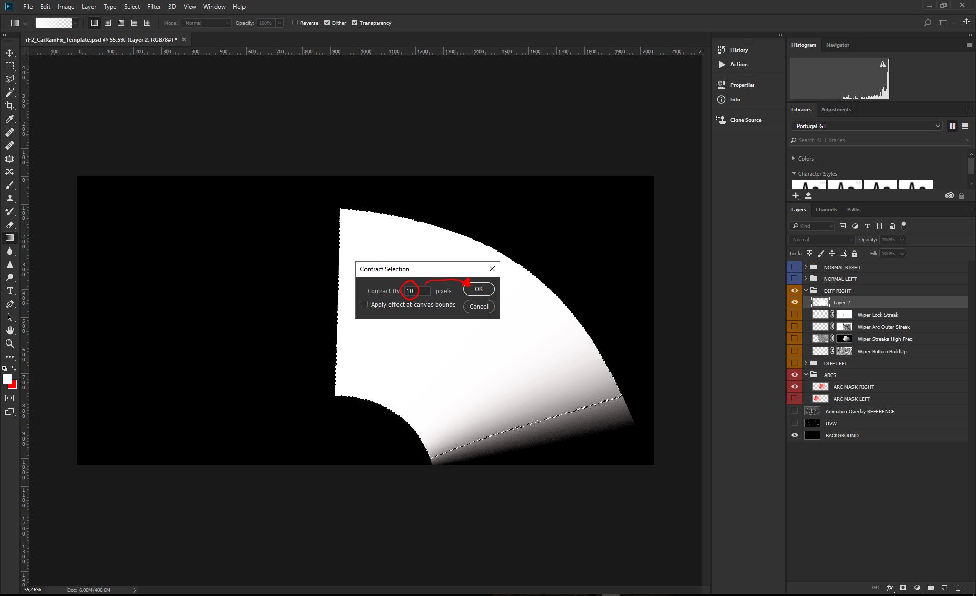
Set the Contraction by 10 pixel and press OK;
With the contracted selection you can now press delete, to remove the internal area of the element;
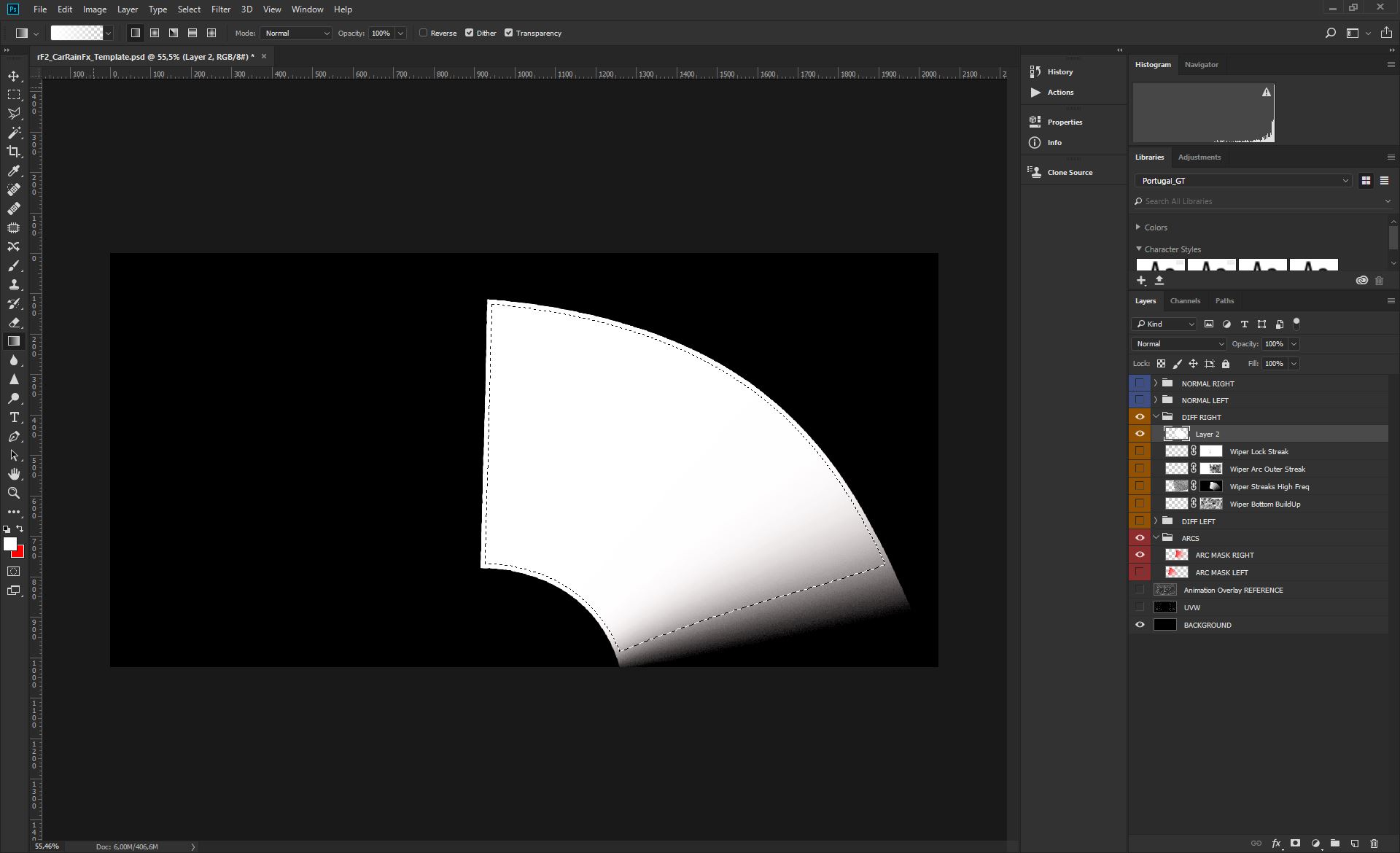
Now we have just need to clean the two parts, as on the picture;
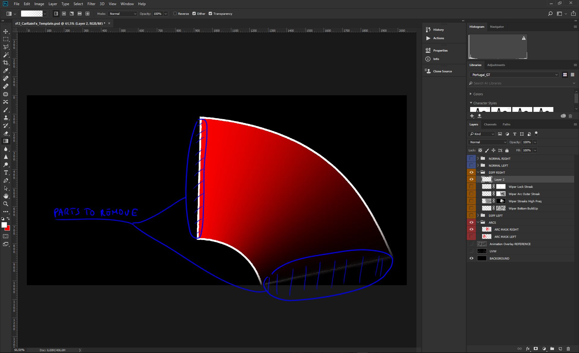
This is what we should get before proceeding and finalize this element;

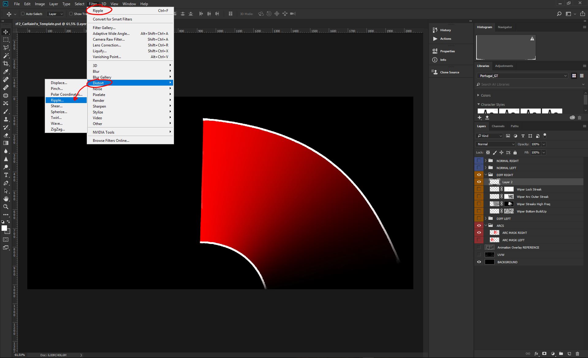
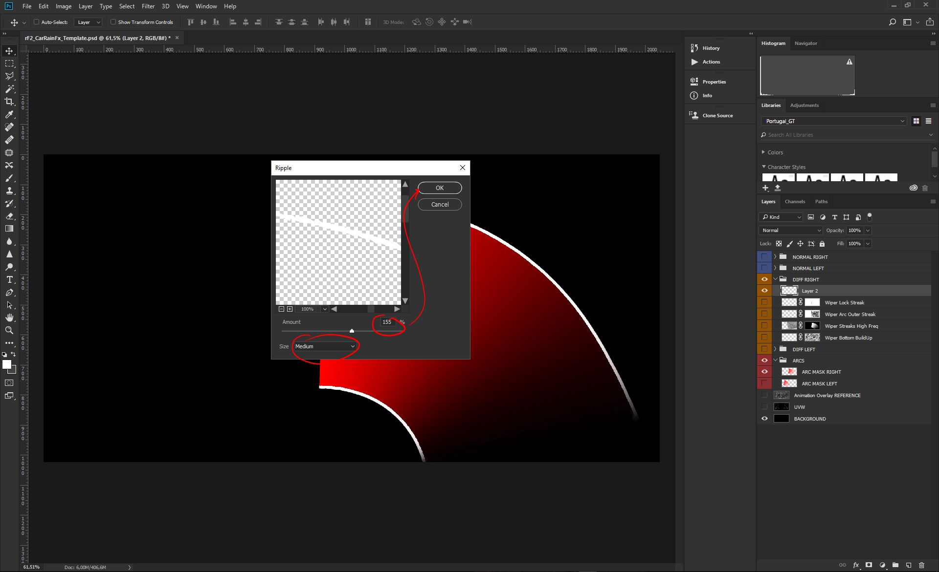
Now we want to give the two streaks a bit of distortion, like a streak of water on the glass. To do so we will apply a tad of Ripple Distortion to the element;
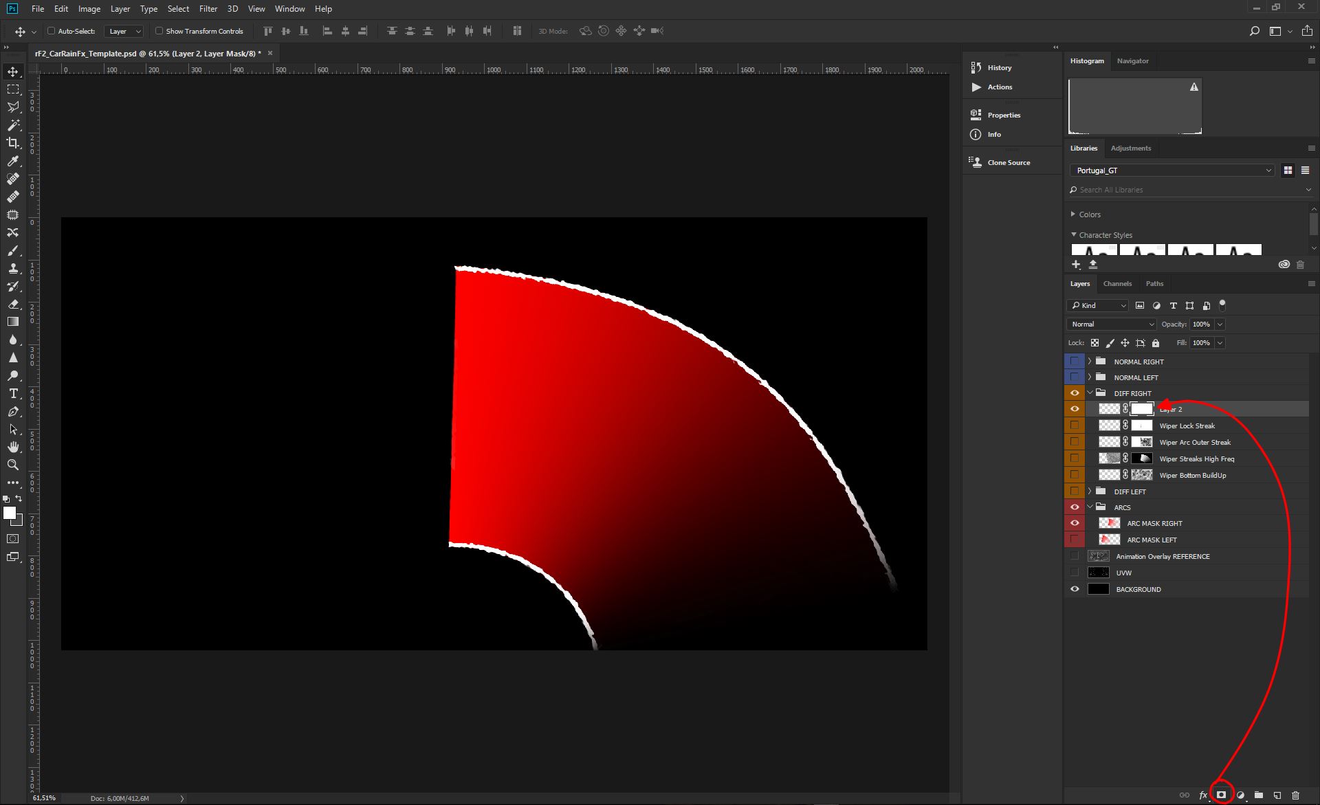
Now, with the Ripple effect done, we want to give the effect a touch of transparency randomness (which will be also usefull for the random threshold in the code). Easy to do, selecting the element layer, and adding a layer mask...;
....and then filling that mask with a Cloud Render, using a gradient of White and Gray to create our random transparency;
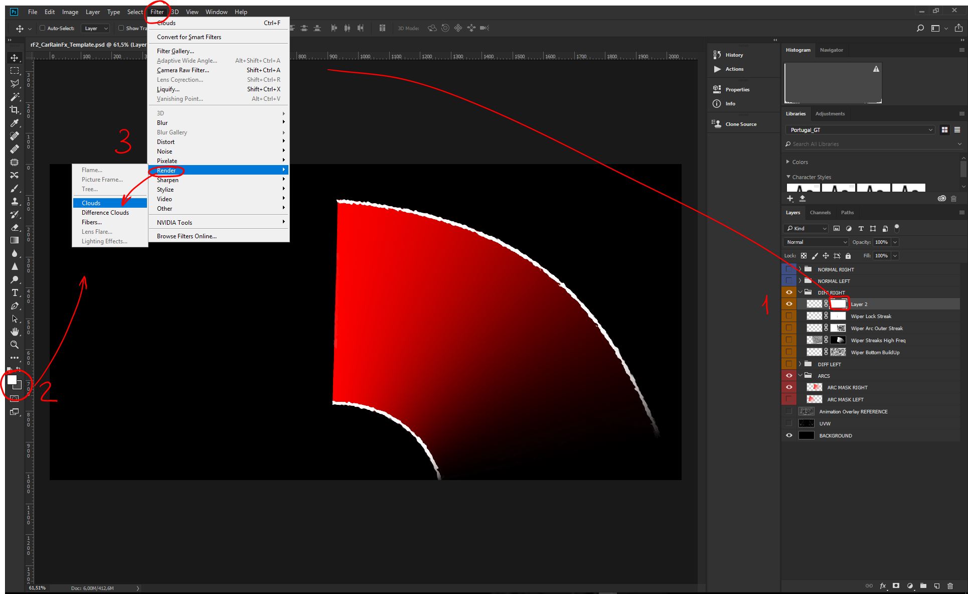
At this point our new element is done and it will appear similar to this;
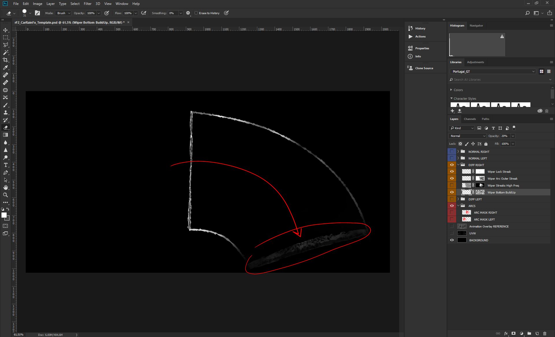
At this point we have the upper wiper lock mark, and the outer streaks. We now need to build the bottom accumulation, and we will use our template element number 2;
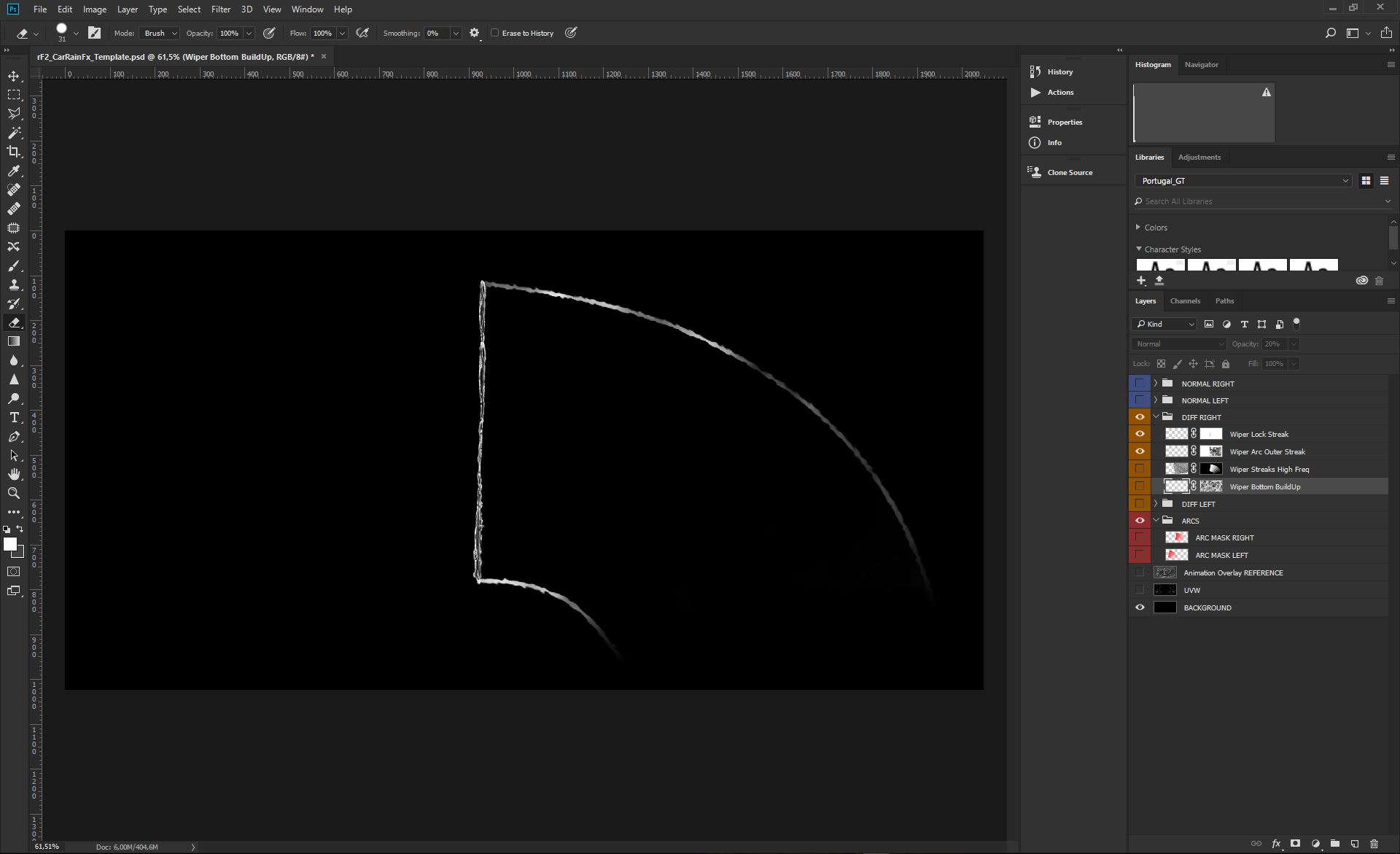
This element should be positioned between the last frames of the animation, when the wiper is still on the windscreen glass, so that we get water effects accumulation on the lower part of the screen. Do not put this element on the last frame, because would be buried under the bonnet, where typically a wiper is parked. Once positioned, be sure the element layer has a Opacity of 20%, always to be part of the threshold randomness;
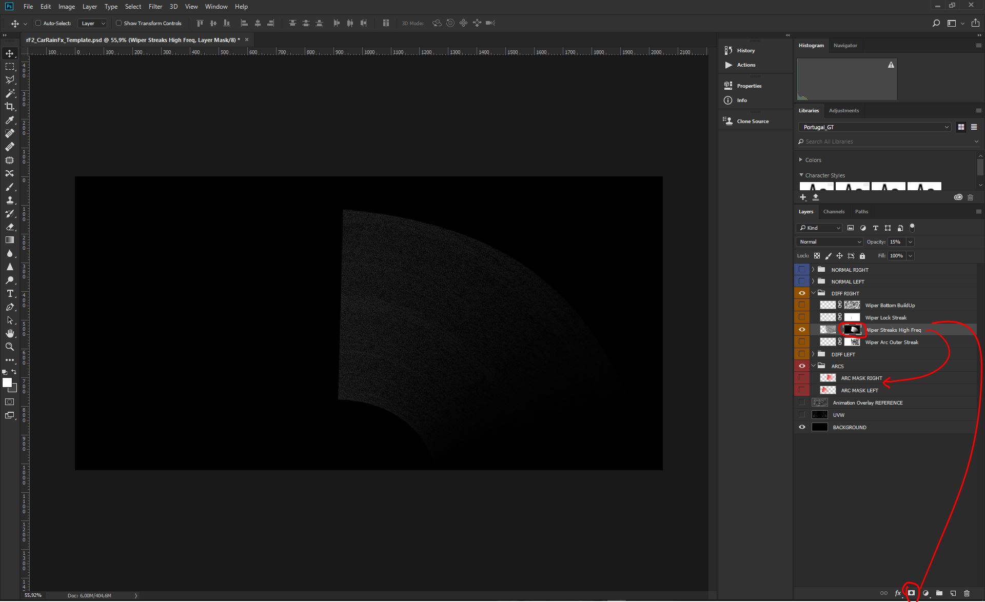
Now we can complete our diffuse for that Arc, with a bit of leftover water spray, along the wiper motion path. We have a Noise element in the Template to be reused for any car. It just does need to be placed/scaled/rotated to match our Arcs.
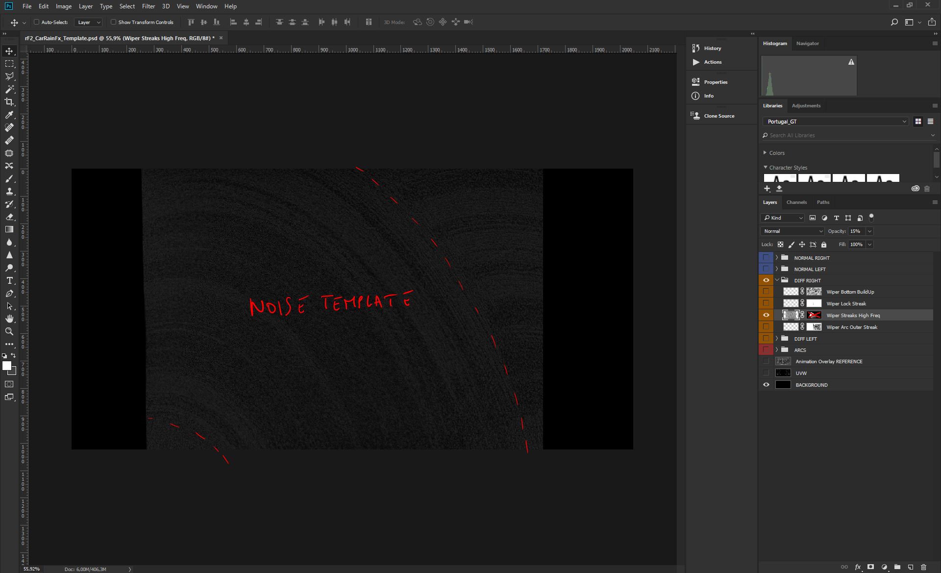
We can copy/paste our Noise element and reuse our Arc Mask to load a gradient selection to be used as a Mask Layer;
Now that we masked the noise layer, we can unlock the mask and turn off the mask too, so that we can manipulate the noise to match the arc, without affecting its mask (see layer setting in the picture);
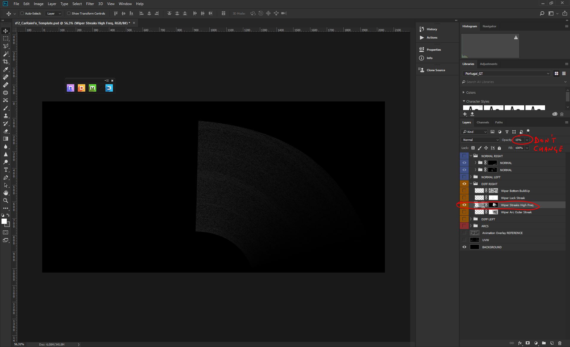
Once we've found a good match between our arc and the noise (for both scale, rotation/direction), we can apply/activate the arc mask. For this layer we will use a 15% transparency because the effect needs to be very subtle and part of the threshold randomness;
Our first diffuse is now ready. Before to proceed with the other arc, be sure that your output is VERY similar to this. It's important that we get a complex mix of transparencies to engage as much as possible the randomness based on the diffuse pixels strenght;
Let's repeat the entire process to produce the other diffuse;
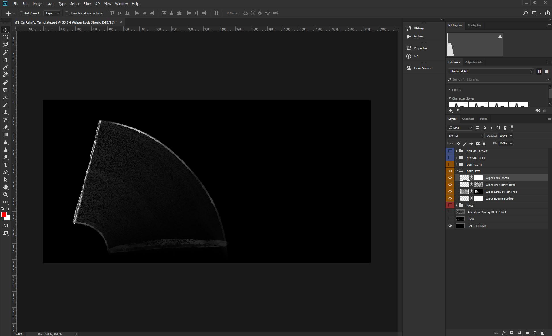
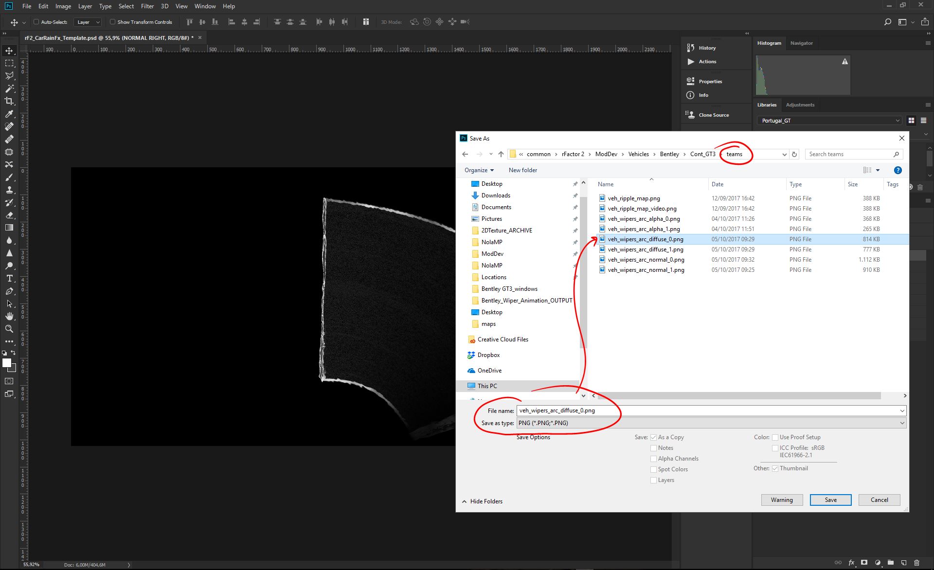
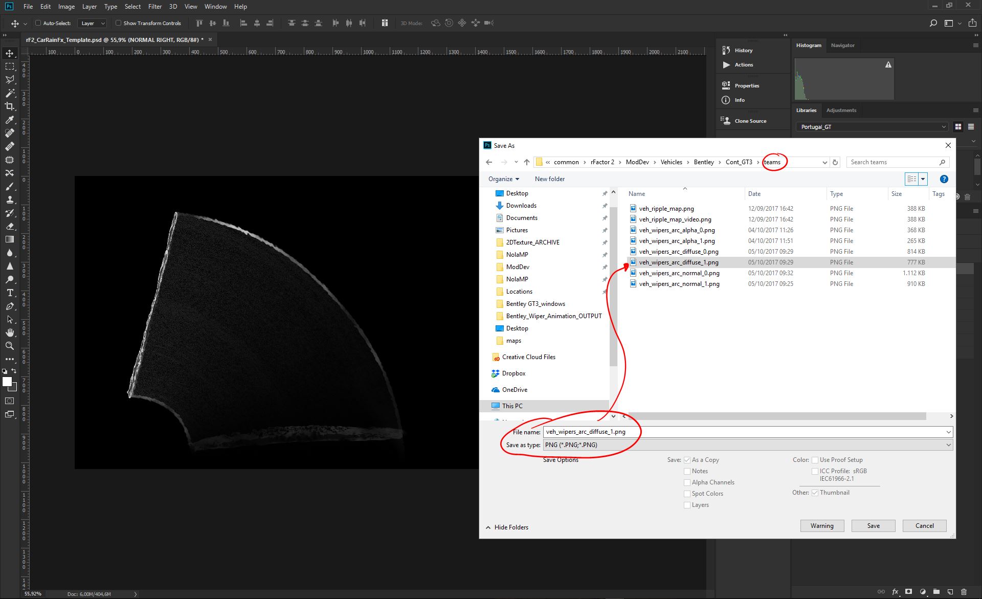
Now you have both Right and Left Diffuse maps, ready to be saved for the game engine. We need a .PNG format, default settings. Both Diffuse needs to be saved into the "teams" folder, of the car mod you are working on;
Names for the files are:
- RIGHT Diffuse; veh_wipers_arc_diffuse_0.png
- LEFT Diffuse; veh_wipers_arc_diffuse_1.png
PS: if you have just a single wiper system, you save just as "veh_wipers_arc_diffuse_0.png"
Last art Task, but probably the more important for the quality of the effect, it's the Normal map generation. Let's move to it!
2.8 - Generate Rain Buildup Normal Map/s
The normal "distortion" is basically the main aspect of the art, that does produce and visualize the water effect on the glass parts. This mean that we want extremely high quality normal maps, with no artifacts, and with proper frequencies for the different we've put on the Diffuse maps.
To achieve the goal we do strongly reccomend the usage of a professional Photoshop plugin, called nDo2 by Quixel, which is part of the Quixel Suite that you can find here; https://quixel.se/suite2/
The Guide will be also using nDo2 to produce the different Normal maps elements, composing the final Normal maps.
For this task we'll be of course using our previous Diffuse maps/layers to be the sources of our Normals. We'll be tweaking their opacity for the task, so remember to reset to their original state when done.
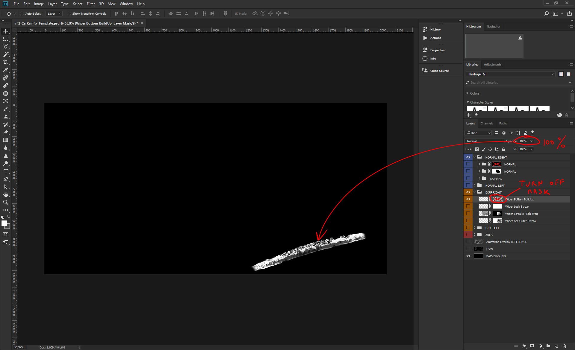
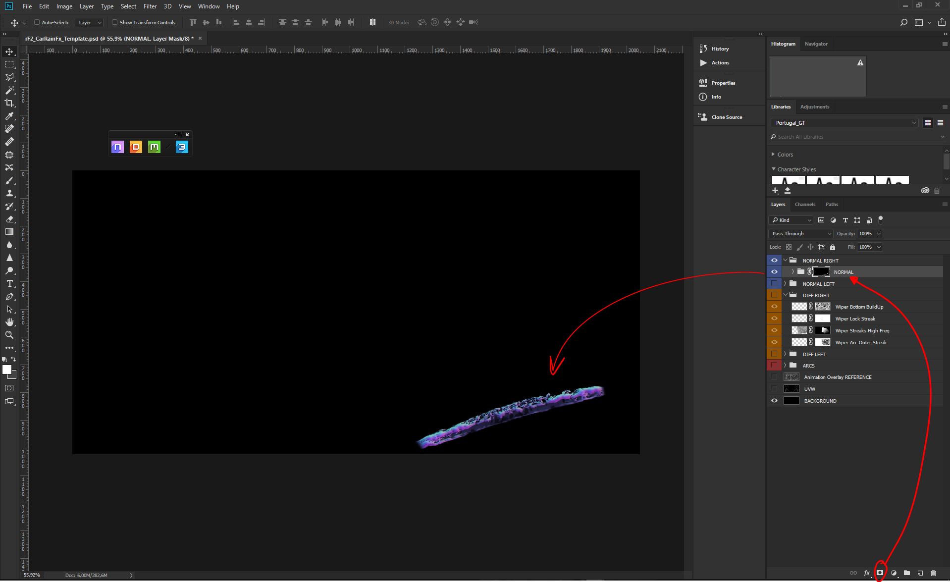
In this Guide we'll be starting from the bottom water accumulation element. We will make it visible on the black background, we will turn off its random mask, and we'll raise the Opacity to 100% to make it fully dense for the Normal conversion;
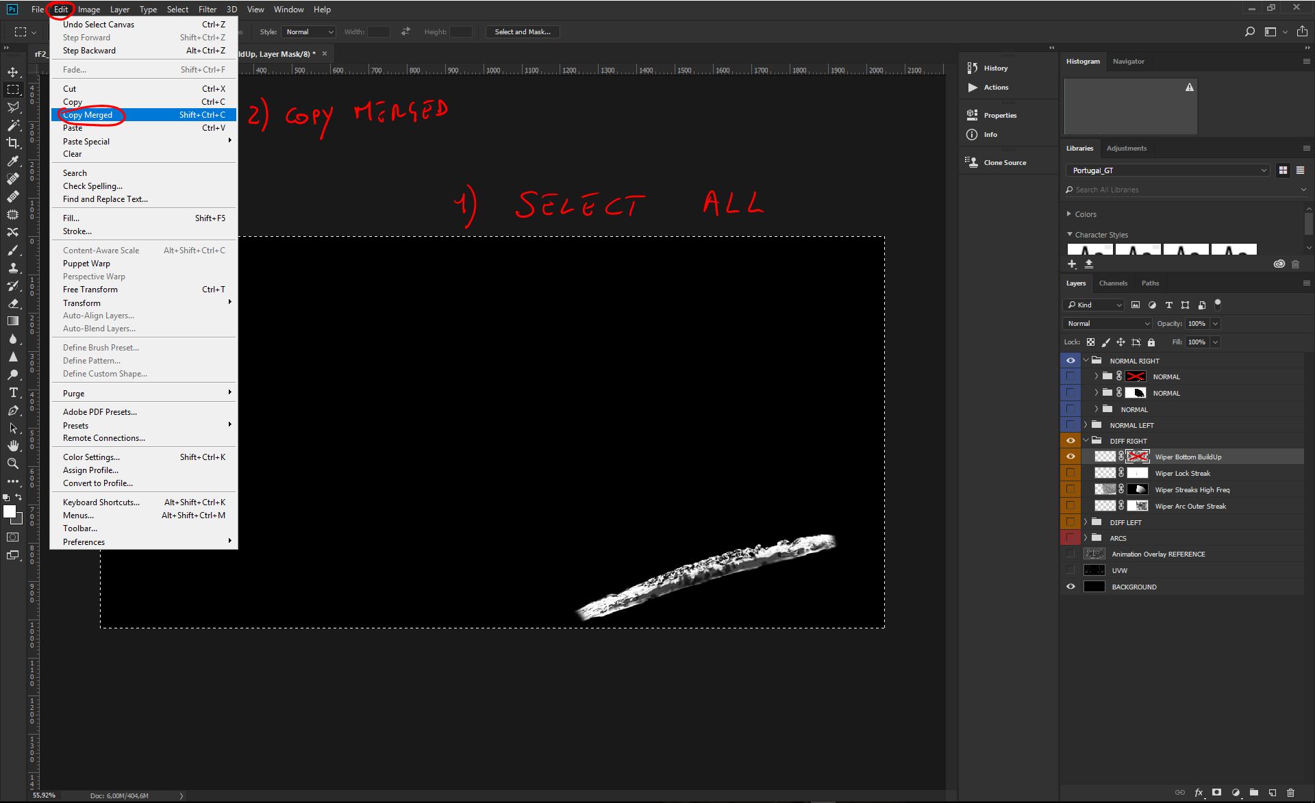
We now need to create a new dummy file for the task, so we'll be Selecting ALL, and using the Copy Merged command to copy everything visible, up to the clipboard;
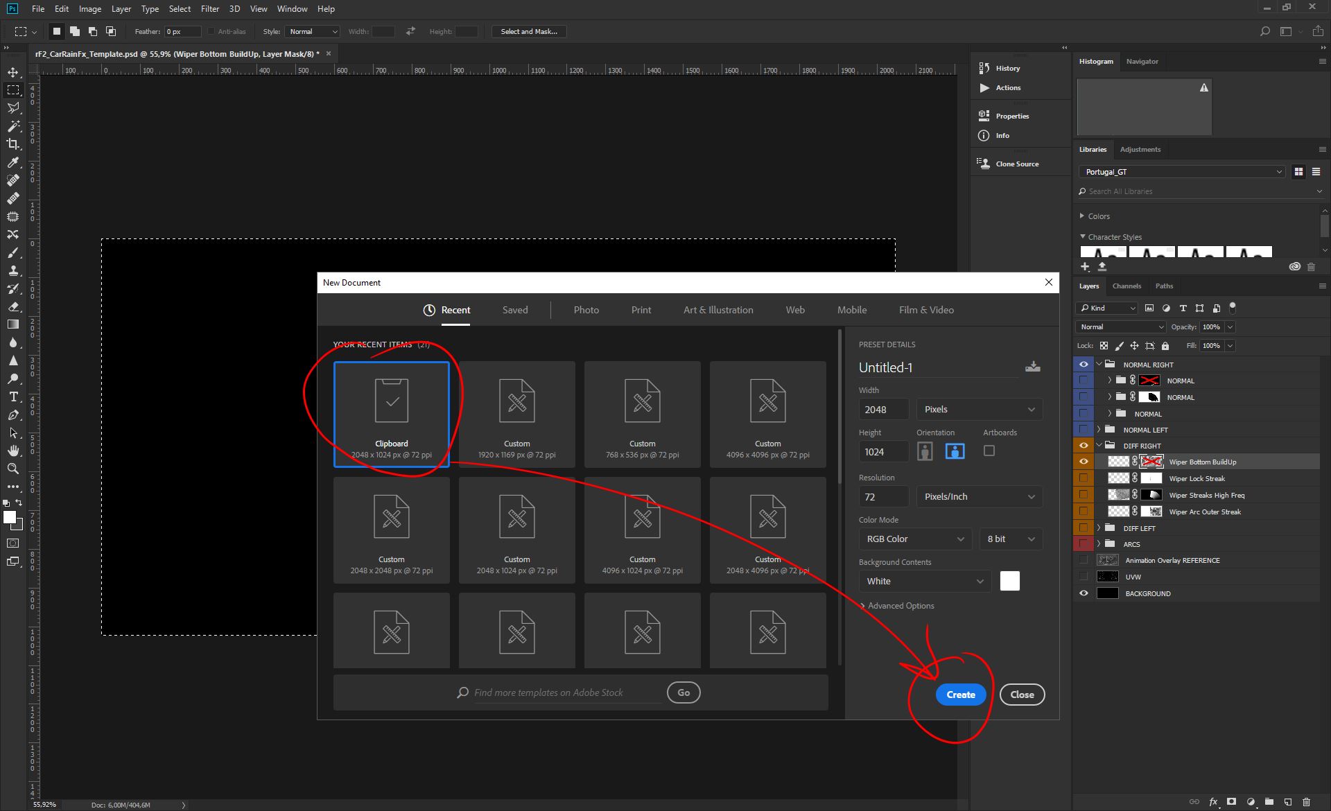
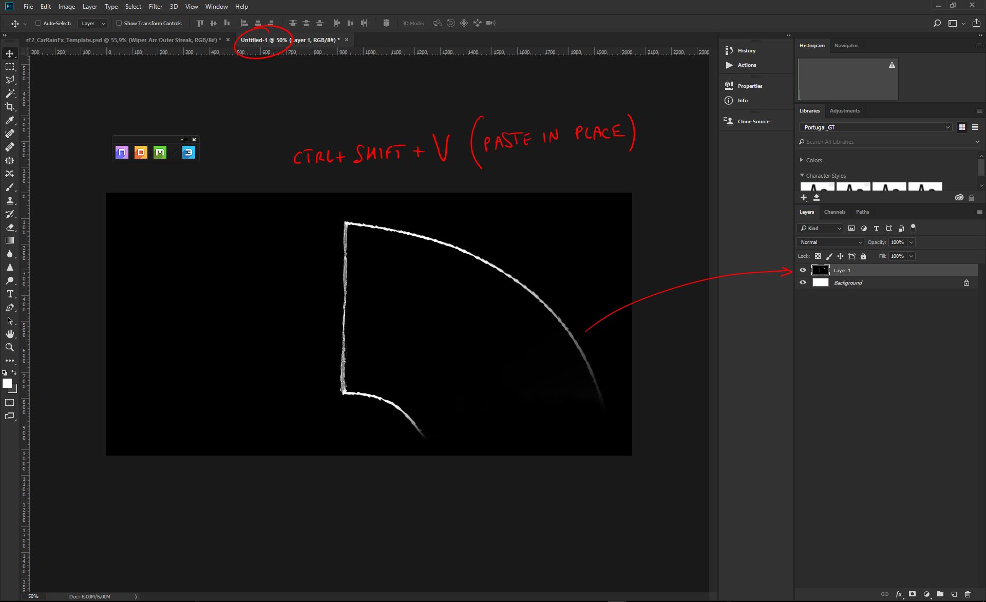
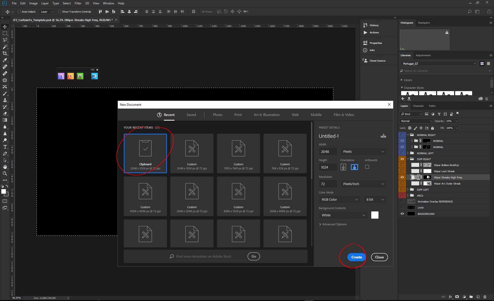
Press CTRL+N to start a new document, you should the panel as in the picture. Clip on the Clipboard to create a new document with the same size of the Clipboard image;
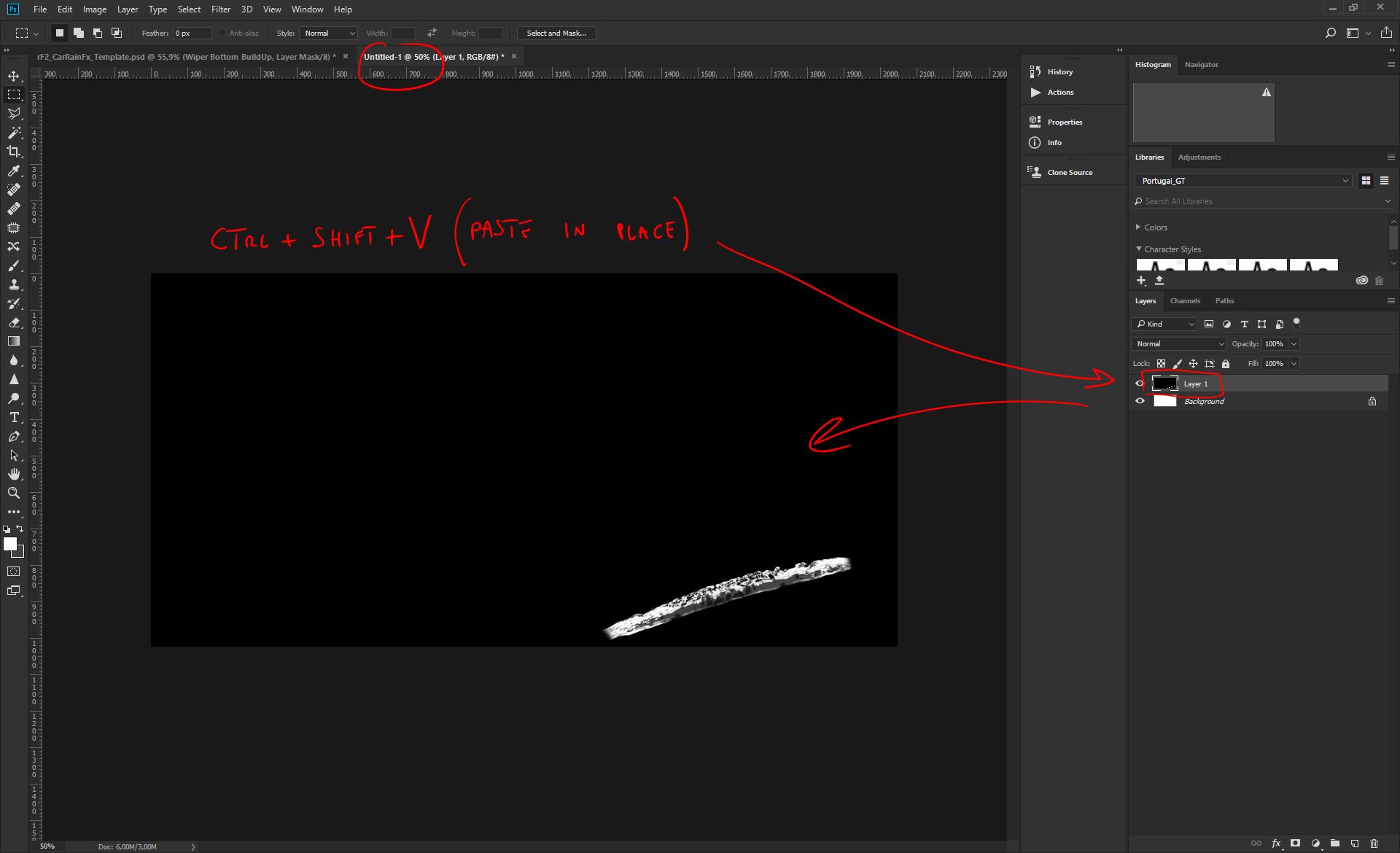
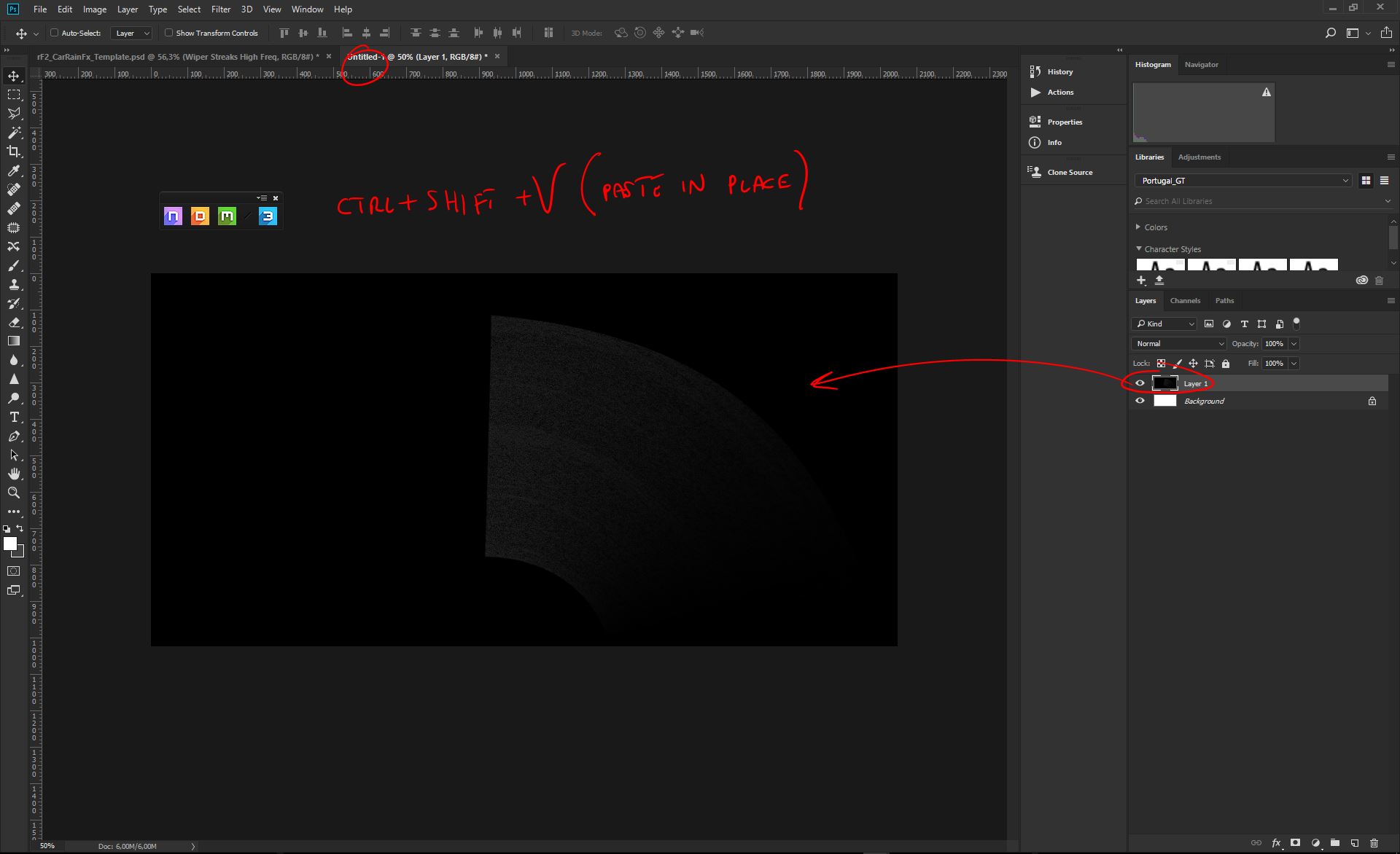
Now that we have created our new document, we can press CTRL+SHIFT+V to paste the merged copy, right in place;
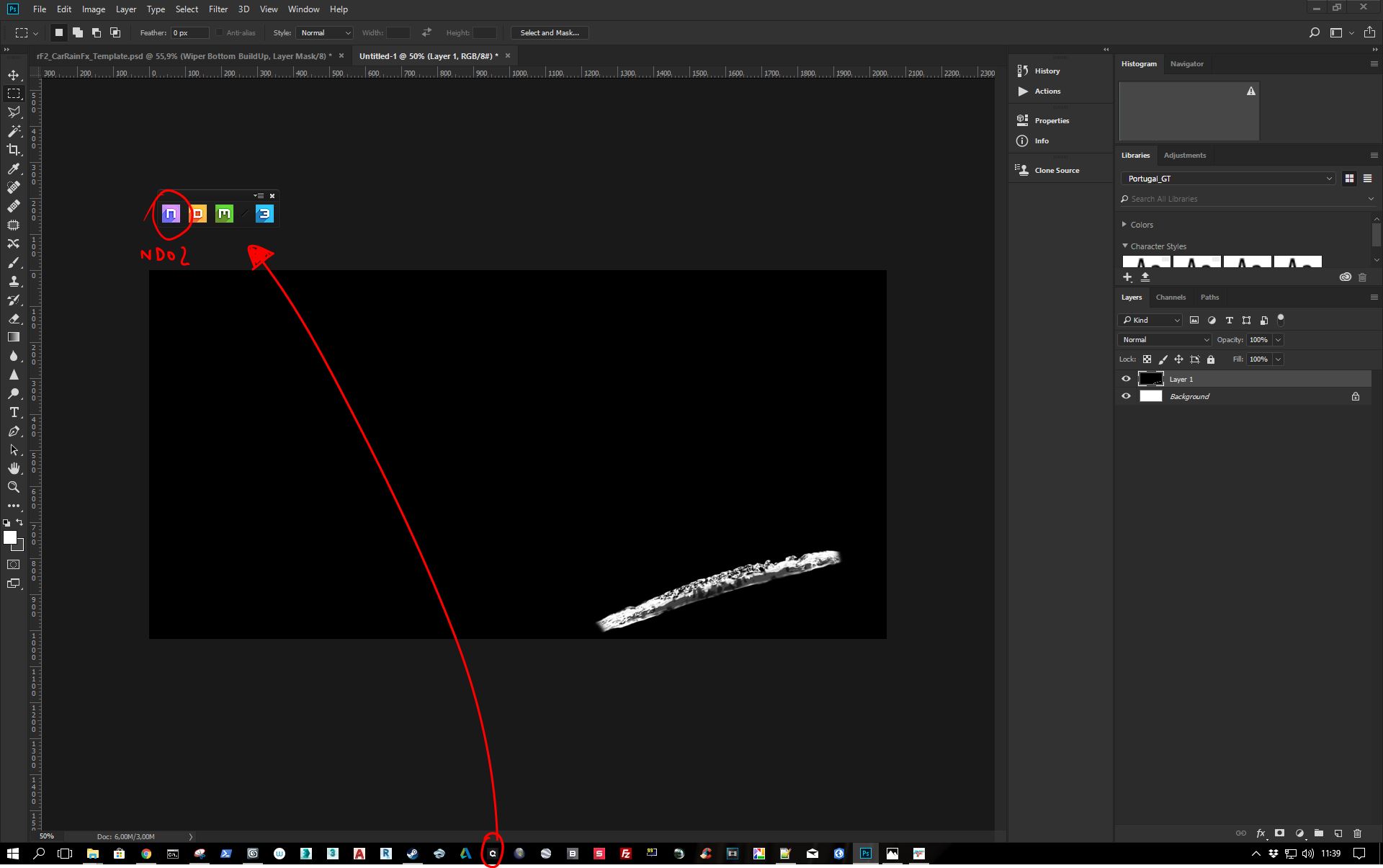
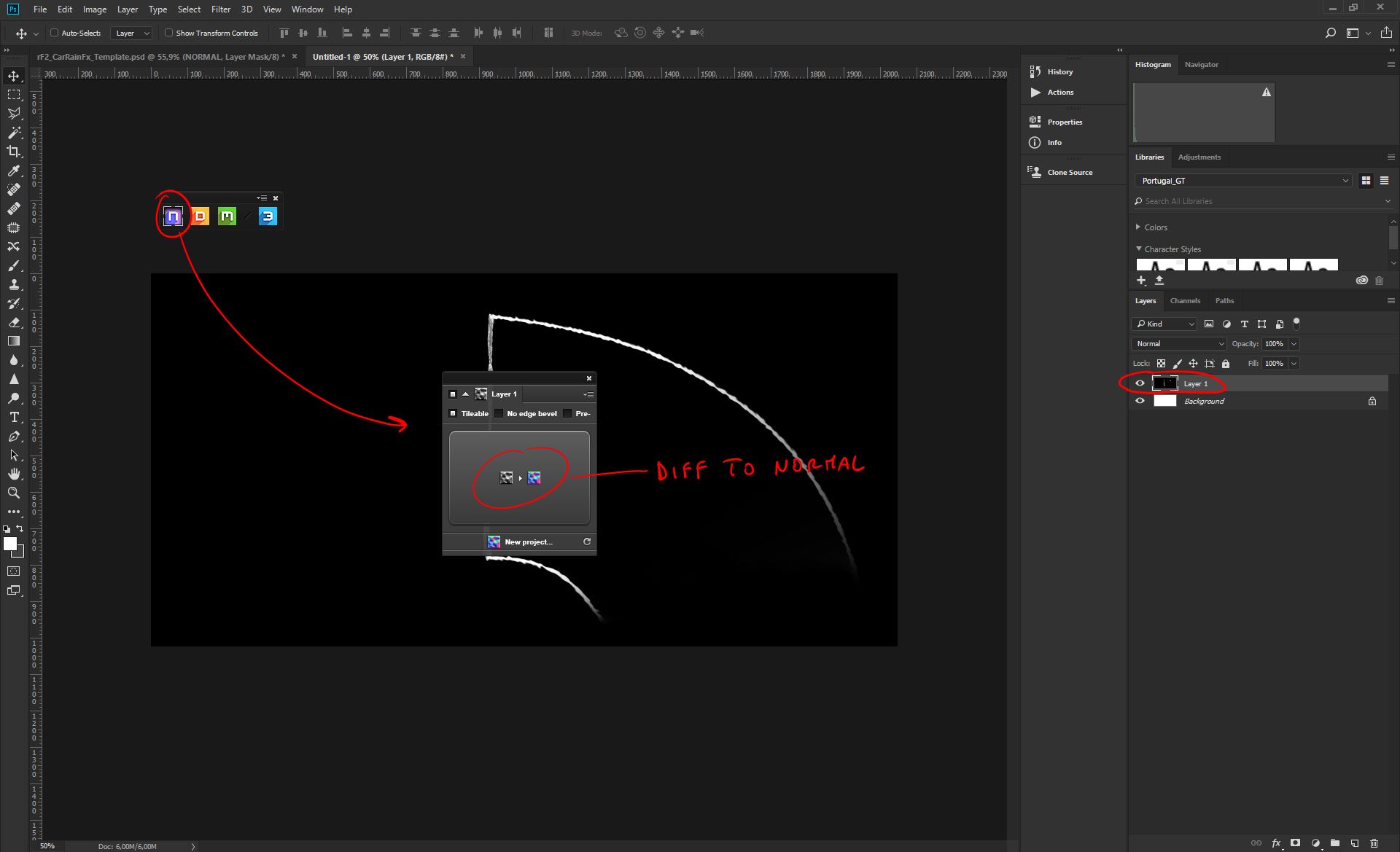
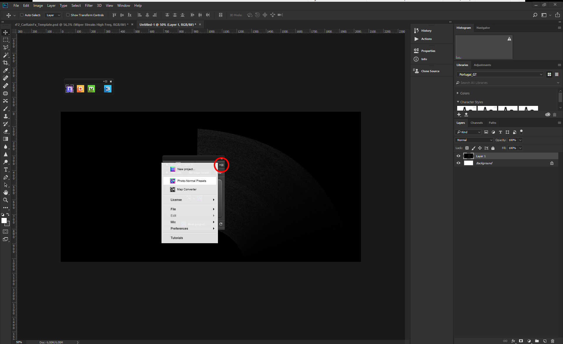
Time to start the Quixel Suite and then click on the nDo2 tool icon, in the Suite bar;
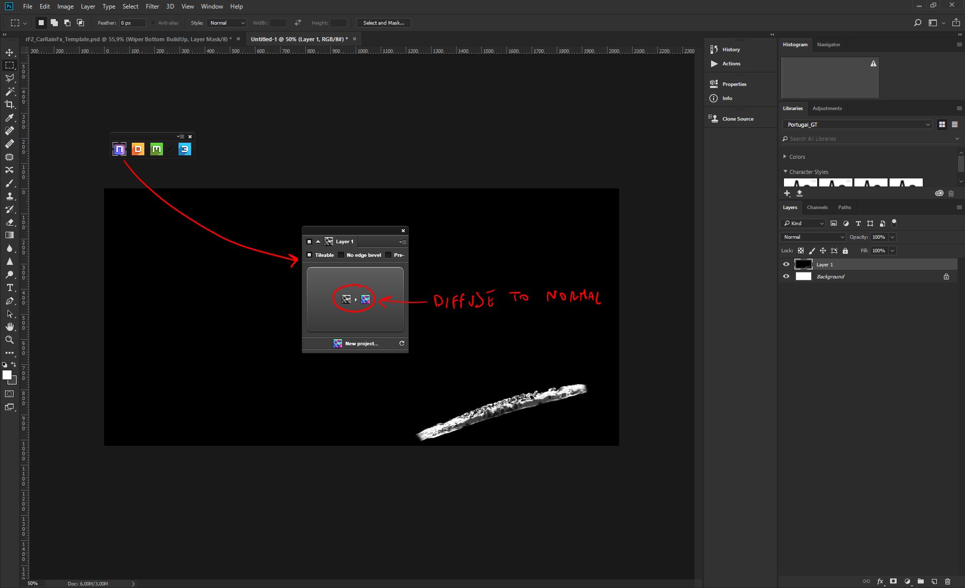
For this first normal, we don't need any special feature for it, since we want all the frequencies to be there. With the diffuse Layer selected, as in the picture, we can just click on the main Diffuse to Normal button, in the main nDo2 interface;
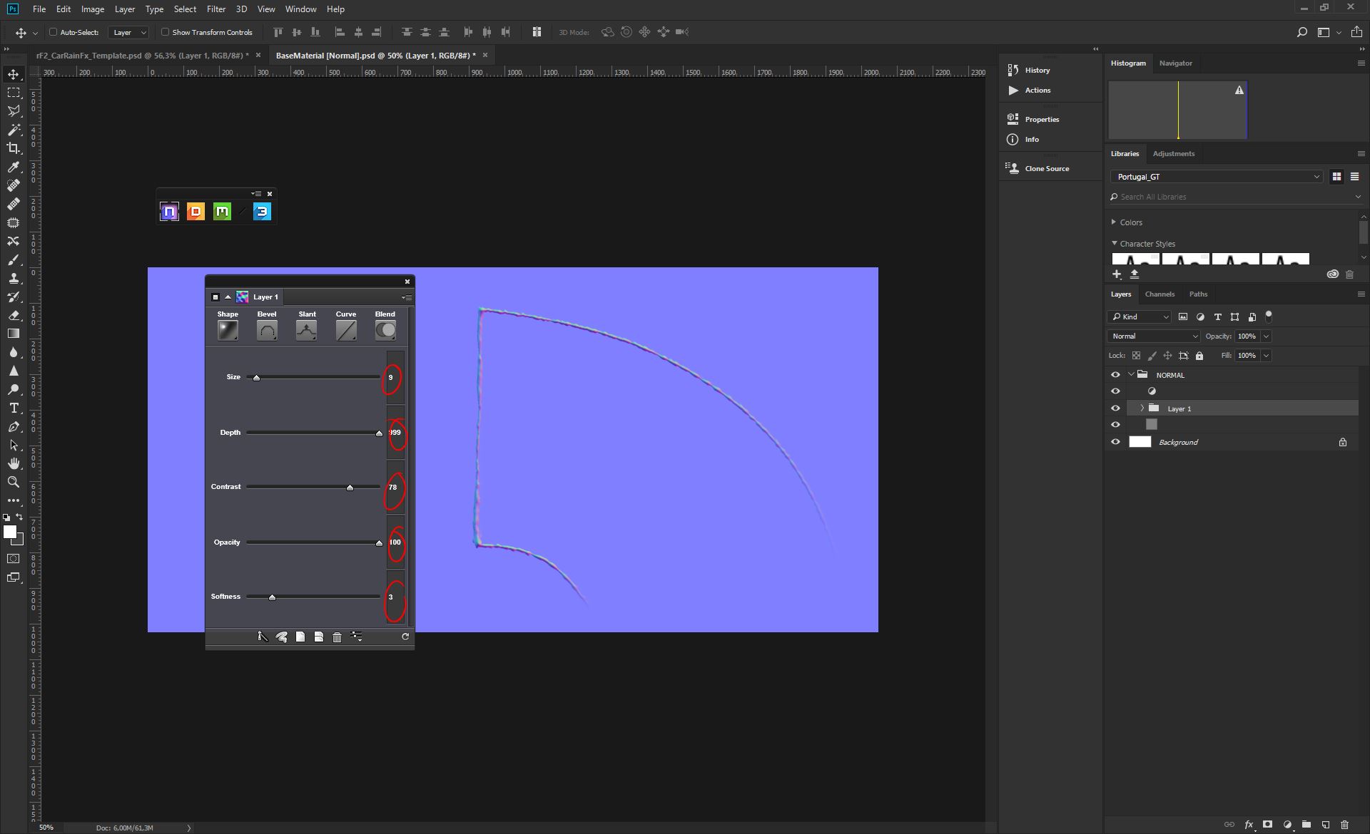
Set the procedural Normal map to be rounder and softer, to look natural. Follow these settings, which are usually good for the purpose;
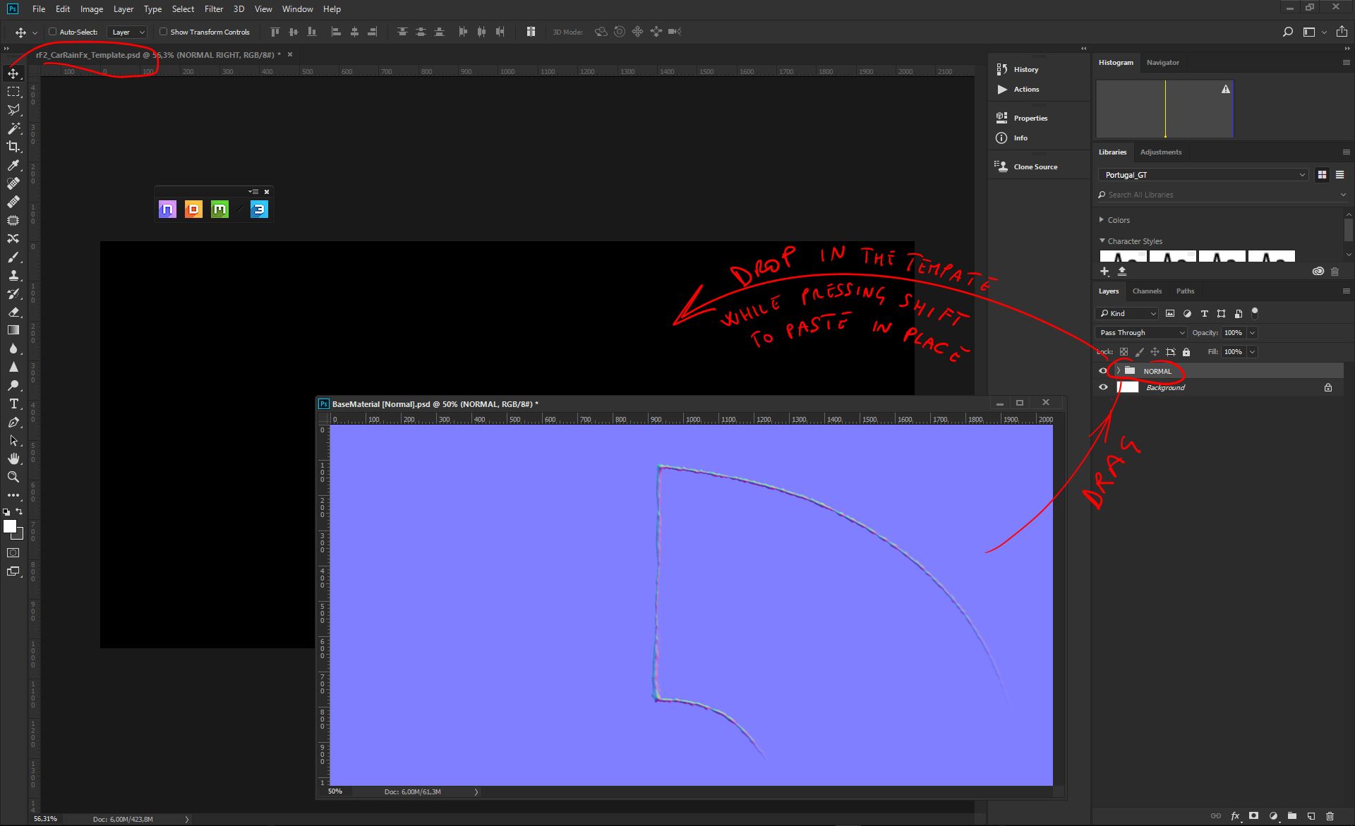
Now that our procedural Normal map is ready, we need that Normal layer group to be moved back to our main car Template document. We can drag and drop that layer group folder, from the dummy document, straight into our main Template. While dragging you have to keep pressing SHIFT key to paste the group layer in place. Be sure it's being pasted in place, to avoid mismatches between diffuse and normals. After that you can either save the dummy document, or delete it;
Now we are back to our Template. Let's be sure we are properly organizing our layers and put that Normal layer groups, that we just created with nDo2, inside a main NORMAL folder. In this case we are working on the RIGHT arc, so we'll call it NORMAL RIGHT;
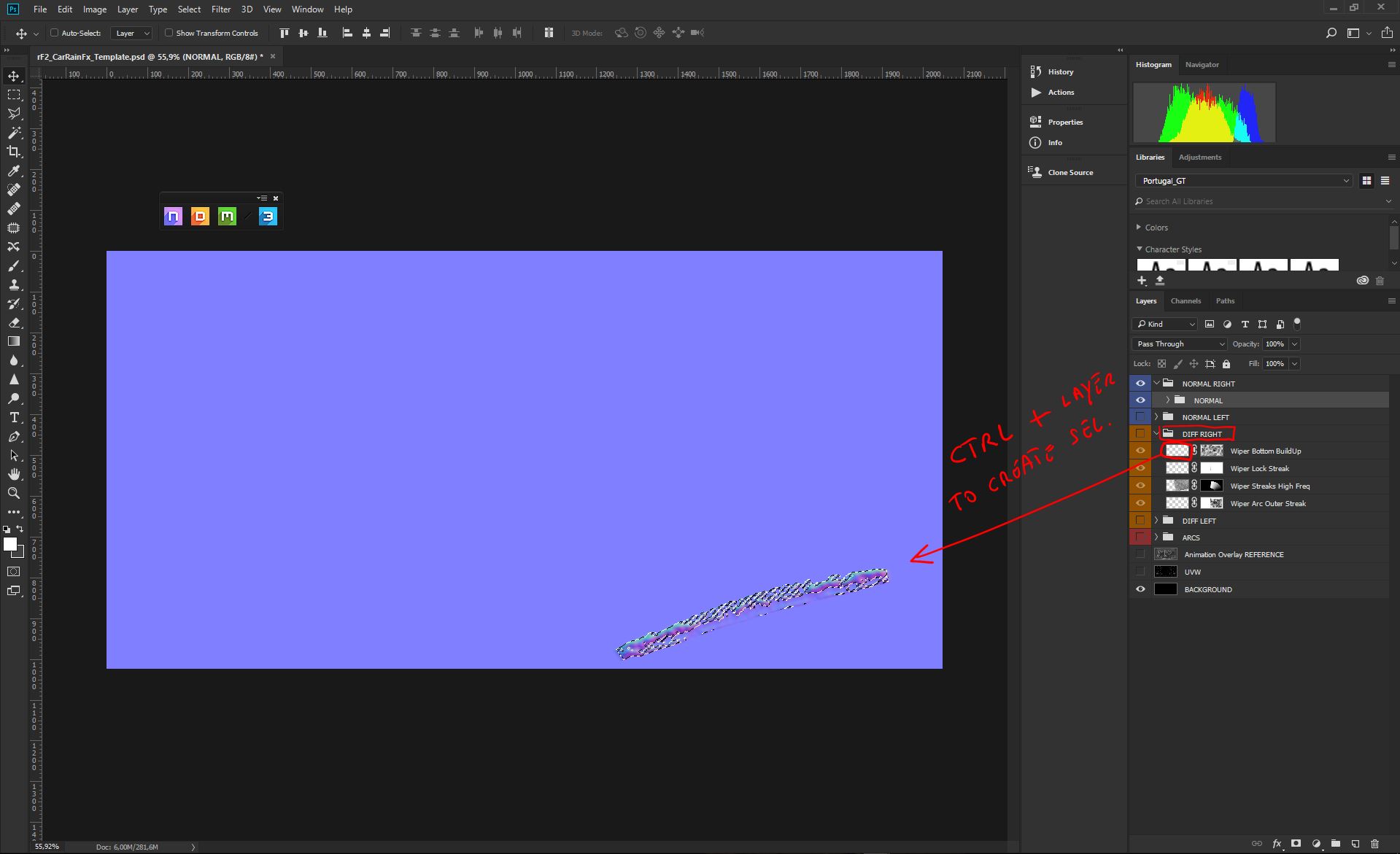
Since we'll be producing dedicated procedural Normal maps for each main Diffuse Element, we'll be overlapping the different Normal folders on a stack. Since this is our first folder in the stack, we'll be masking this normal so that it will mix with the next we'll be producing, and placing underneath, in the stack. To do so, we have just to create a selection from the diffuse element, clicking on it, while pressing CTRL. After that, with the Normal layer group selected, we'll be generating a Layer mask, as in the pictures;
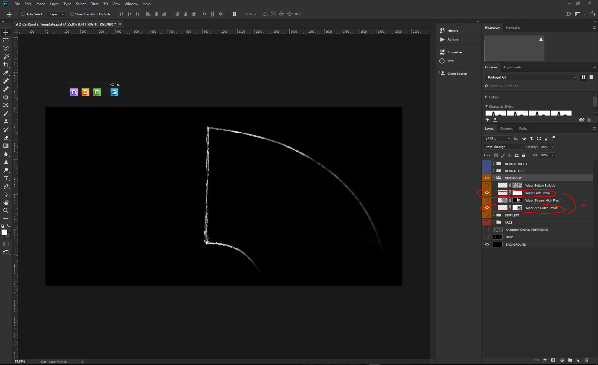
We can now select both the Wiper Lock Streak and the Outer Streaks, because they are both similar frequencies (edgy and thin);
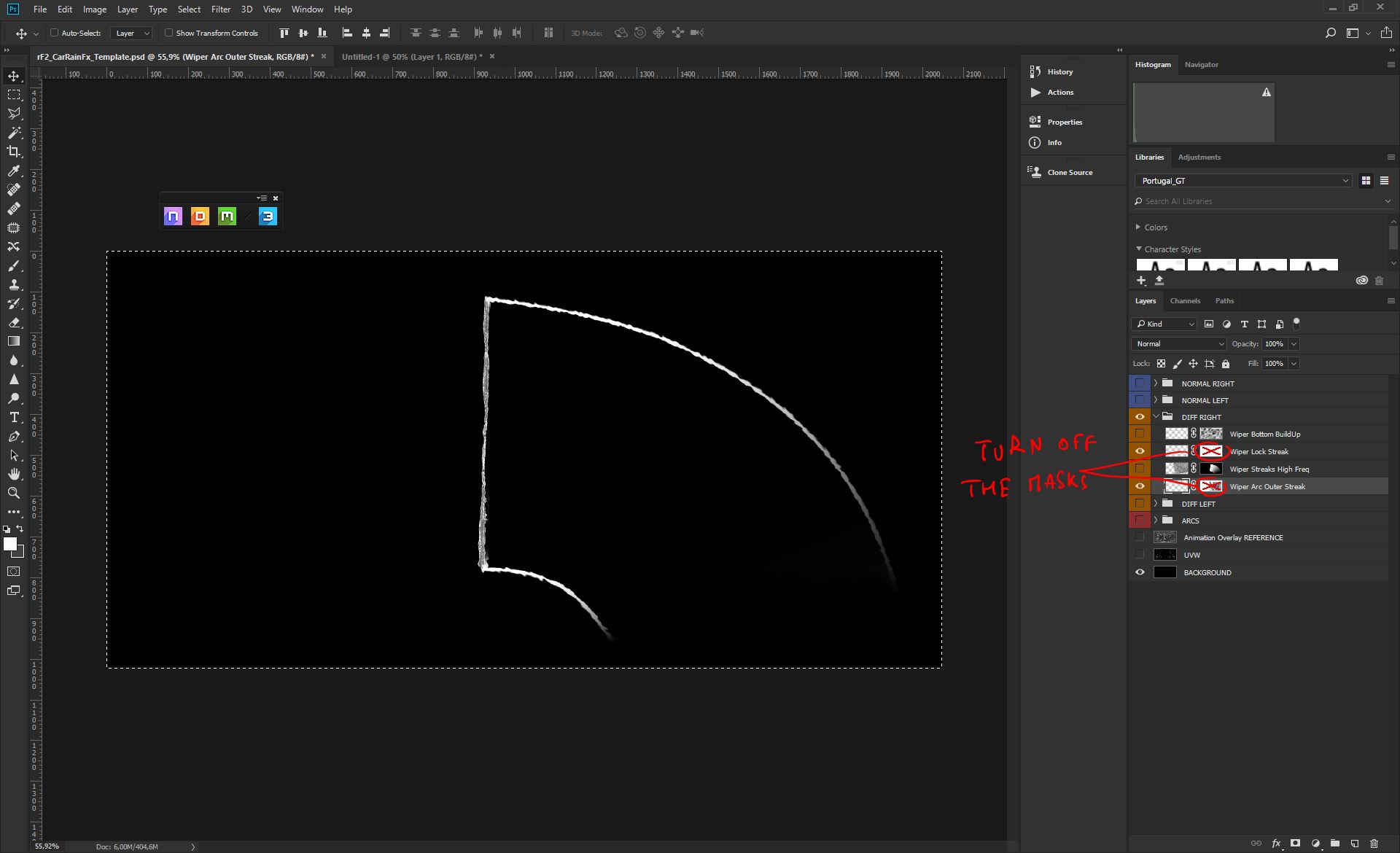
As before, we don't want any Cloud Mask for the task (diffuse to normal), so we will turning off both Layer Mask and get a full solid diffuse (remember to reset to default before to save your Template);
Same as previous passage, we'll be now selecting all it's visible in the canvas, and Copy Merged to send this up to the Clipboard;
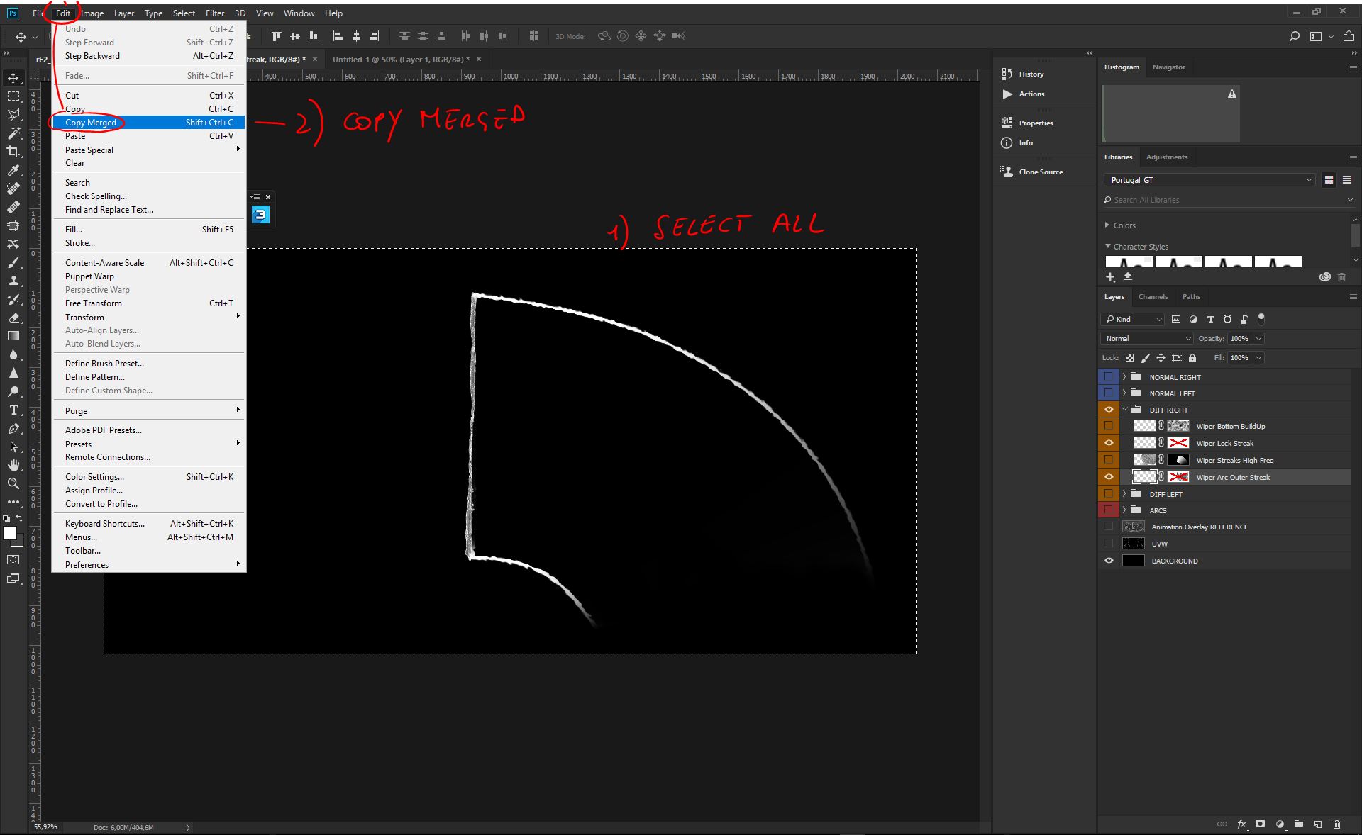
CTRL+N it will open the New Document panel, click on the Clipboard content to start a new dummy document with same size as the original one. CTRL+SHIFT+V will paste the Clipboard in place;
Start the nDo2 clicking on the Quixel Suite Bar, and - as before - we'll be converting the diffuse to a procedural Normal Map. Be sure you've the layer selected, as in the picture;
We want this similar to the previous element, just a bit more edgy. The settings in the picture will help us in the goal;
Close the Normal folder and Drag & Drop from the dummy document to our Template, while pressing SHIFT so that we're sure to paste in place;
Let's not sort that latest Normal folder, underneath the previous one, as in the picture. You should see the first Normal element we did, on top of that last Normal, as in the picture;

Now let's create masks from the diffuse elements, so that we can see underneath, where we will place our last procedural Normal map, for the Noise;
Now let's turn on the Noise Layer, but this time we'll be NOT touching its original opacity, since we really want a very subtle noise Normal;
We did that already lot of times, right? ![]() Select All visibile stuff in the canvas and copy merge;
Select All visibile stuff in the canvas and copy merge;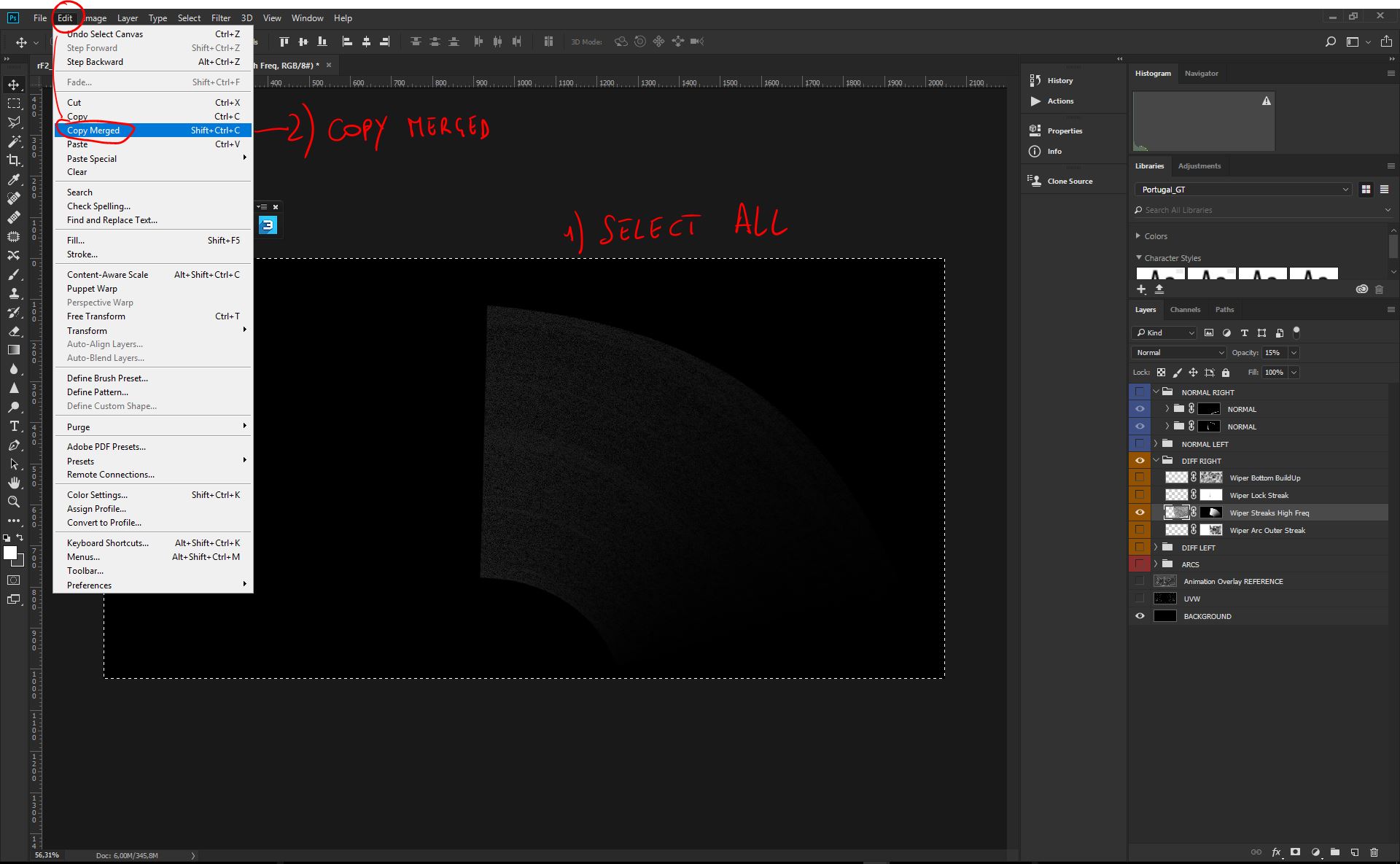
CTRL+N to open the New Document panel. Pick on the Clipboard to create a new dummy document with same size as the Clipboard;
Let's paste the Clipboard, with CTRL+SHIFT+V (paste in place);
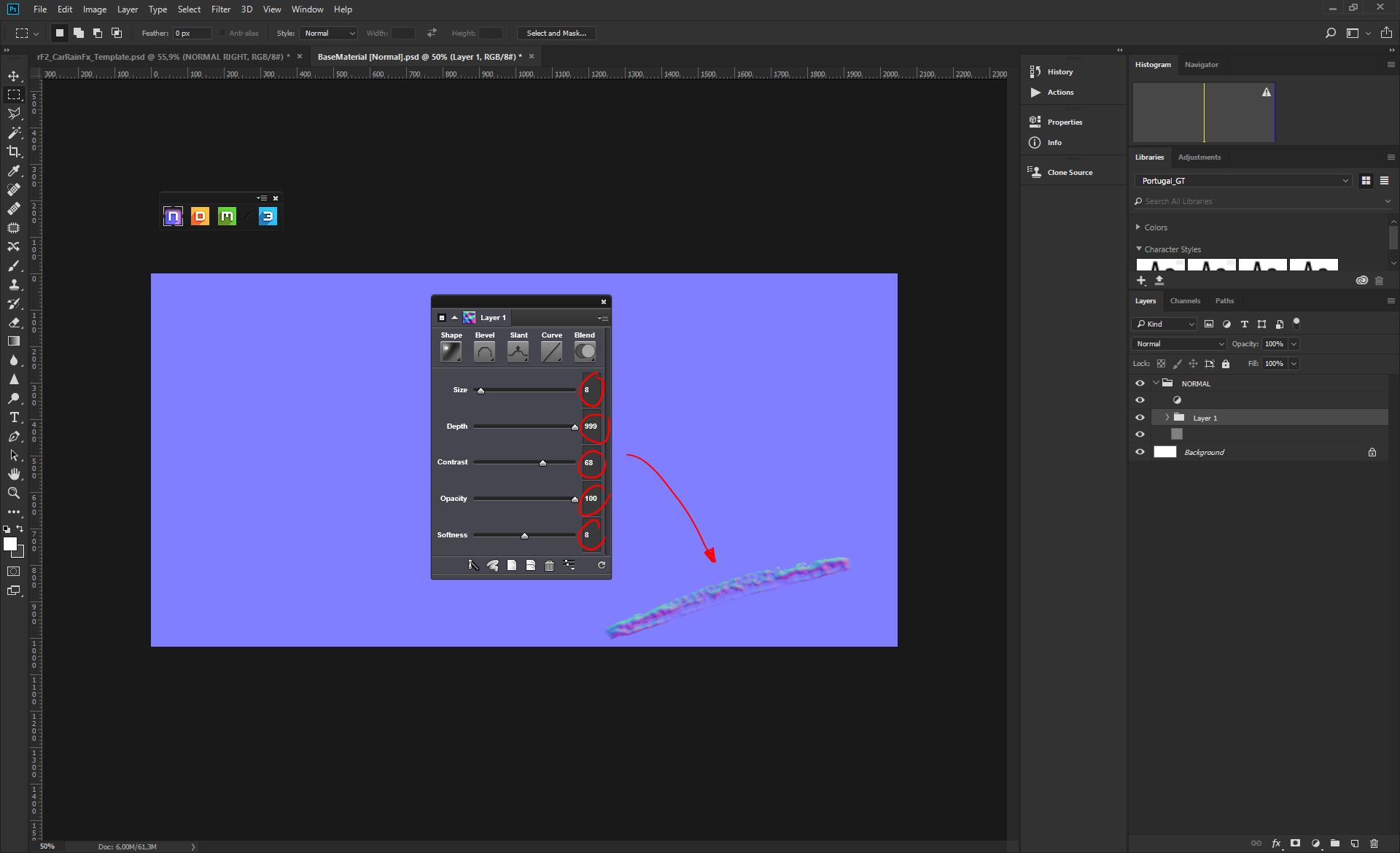
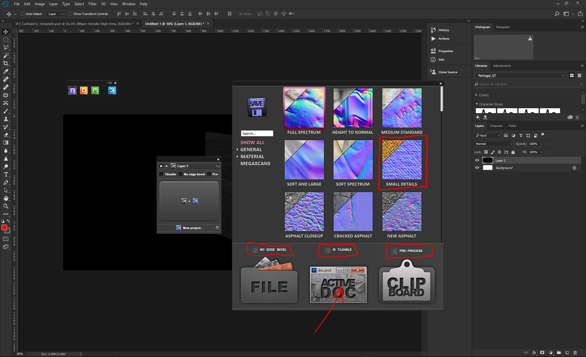
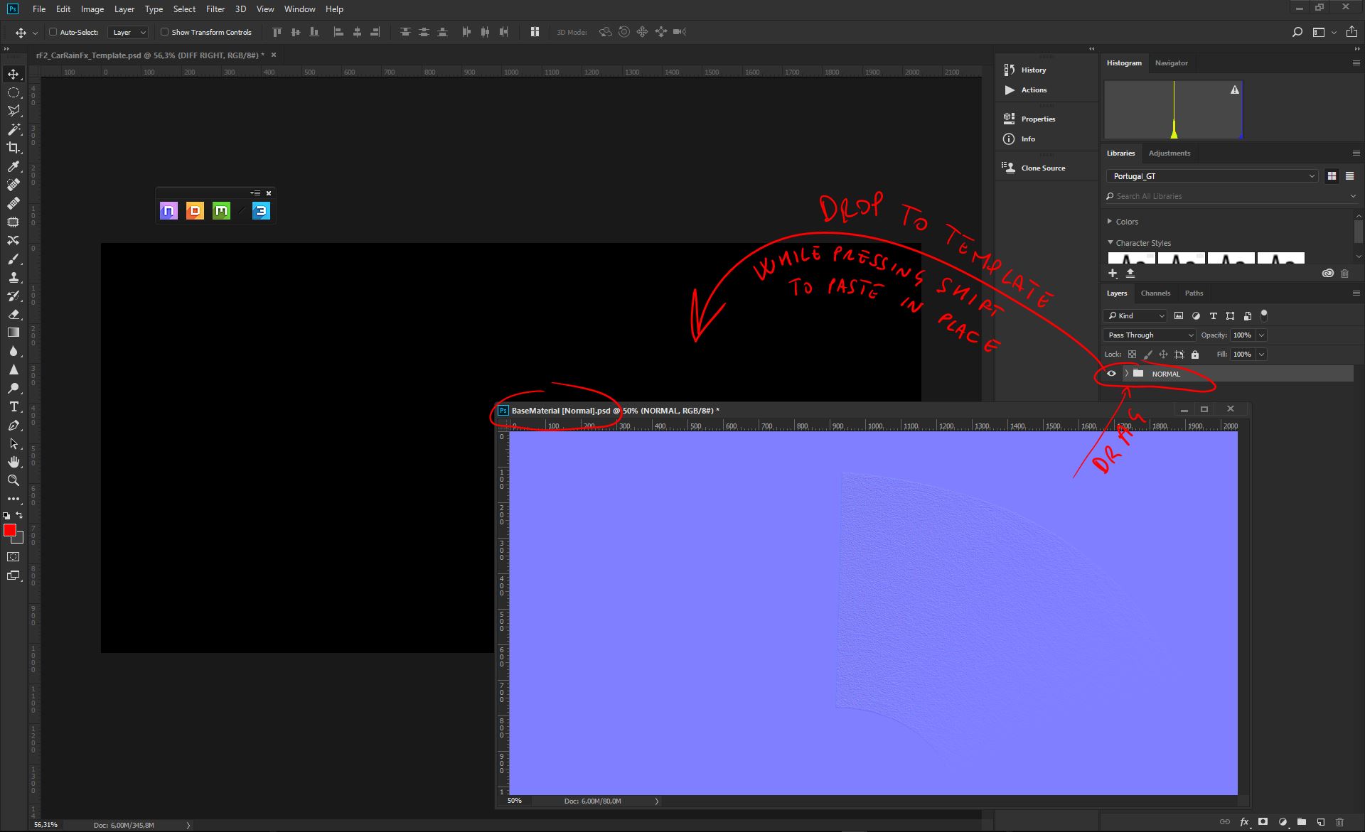
Launch nDo2 from the Suite bar. This time we need a very high frequency normal with sharp details. The Diffuse to Normal this time isn't good enough, so we'll be using some of the specialized Photo-Normal Presets we have available from the Top/Right rolldown menu;
We'll be picking the "Small Details" Preset, since this is the best in the pack to extract the sharper details we need for the noise. Let's use same settings as the picture, and when ready press on Active Doc. This will render the new Procedural Normal map, but this time nDo2 will run a new document, away from the dummy you just created;
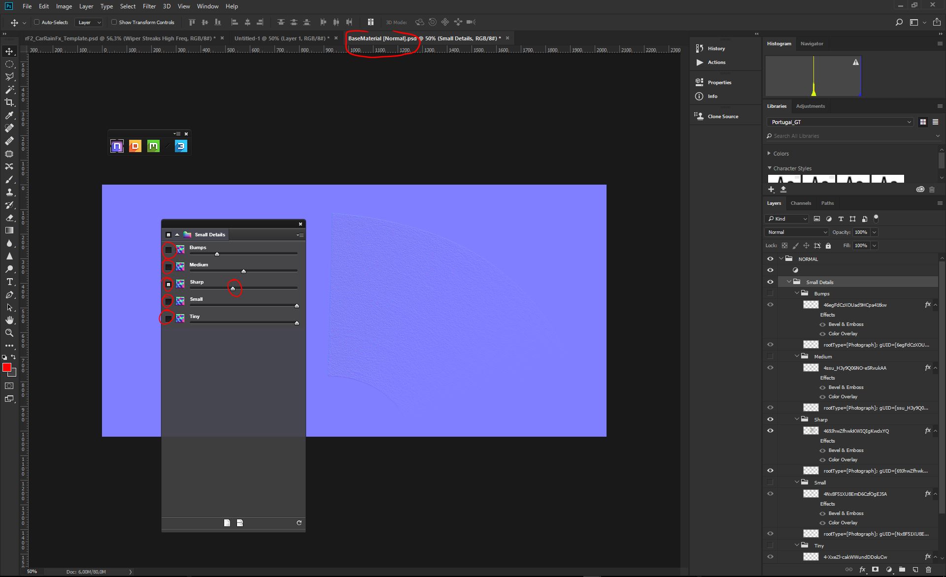
As you can see, we now have a new BaseMaterial[Normal].psd, just created by the nDo2 Algo. From the Small Details panel, we'll be picking just the Sharp layer, turning off everything else, as showed in the picture;
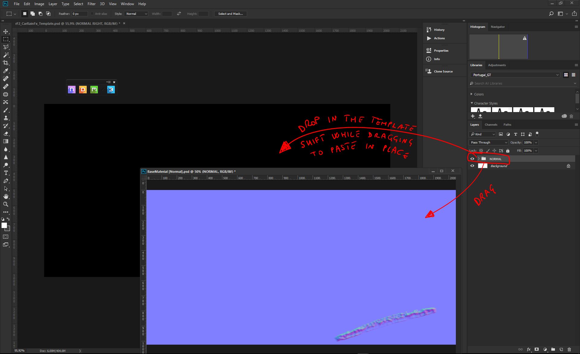
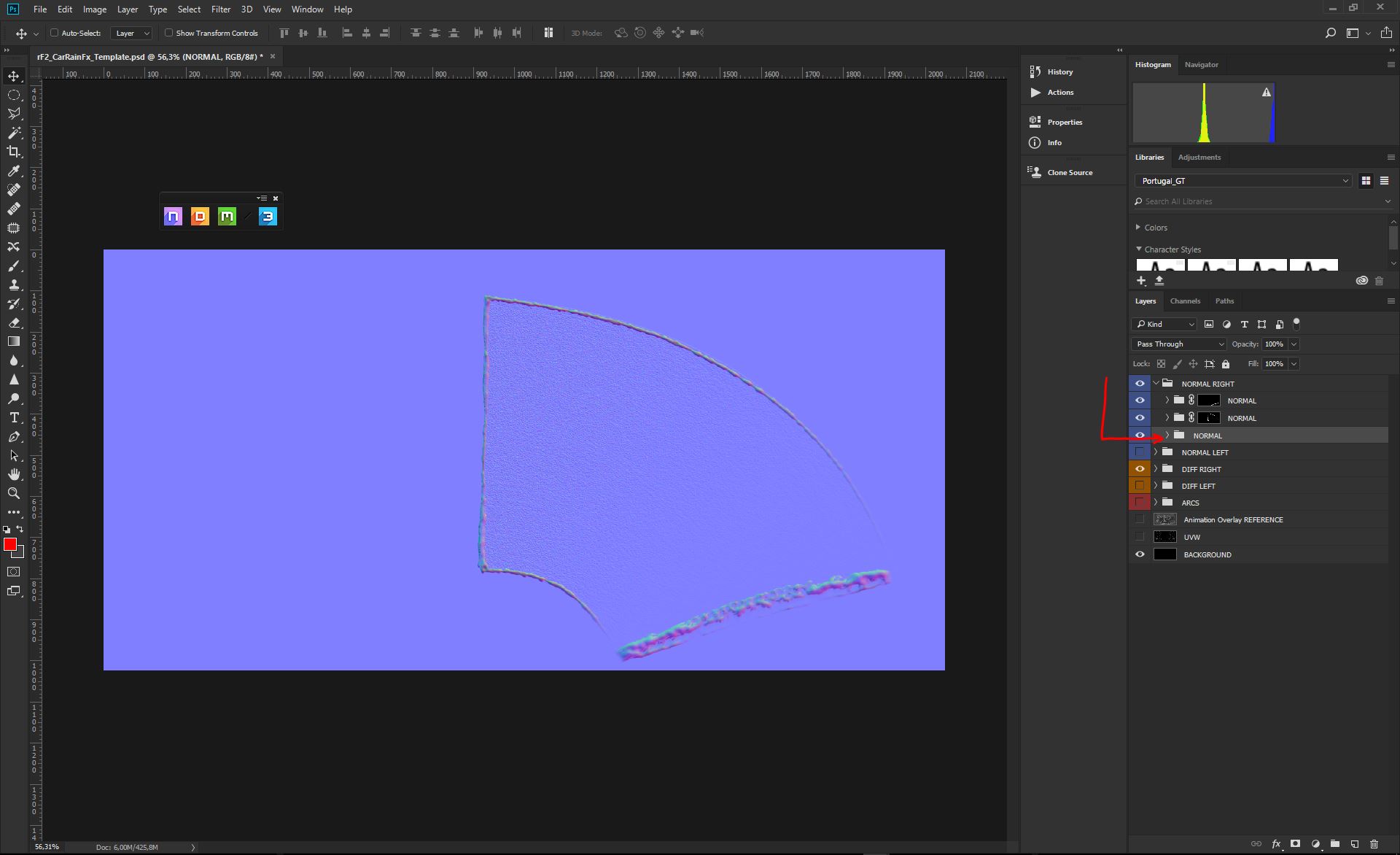
Let's Drag & Drop our new procedural Normal map, straight into our main Template, while pressing SHIFT to paste in place;
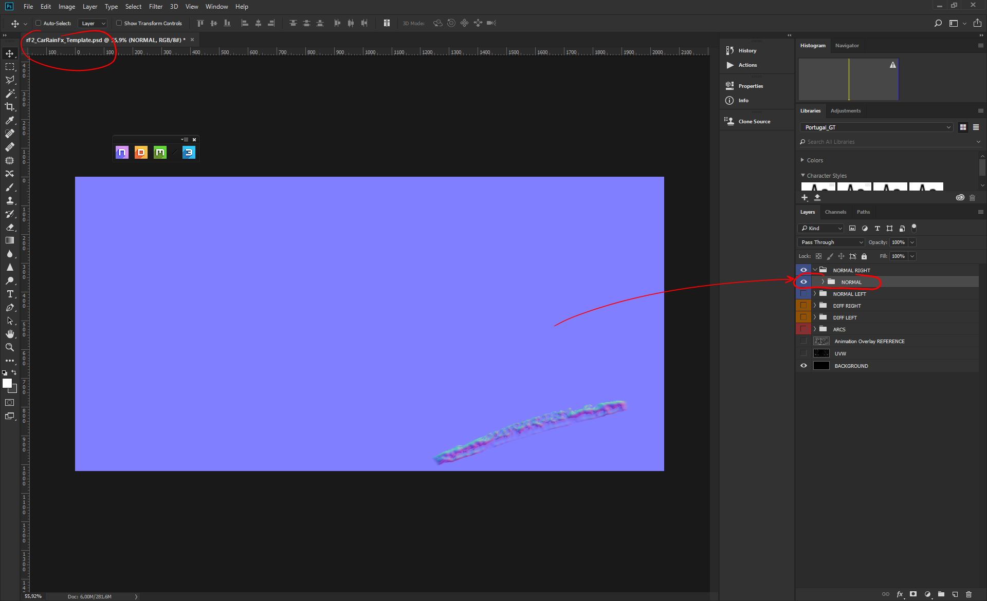
We can now move that Normal folder just under previous 2 Normal folders, so that it will be our "base". We don't need to mask this last one, since we want the Normal flat base to be there;
Now we can reproduce all the previous passages to create our Left Normal set. Feel free to add a bit of variation here and there, so that we have two main sets with subtle random changes;
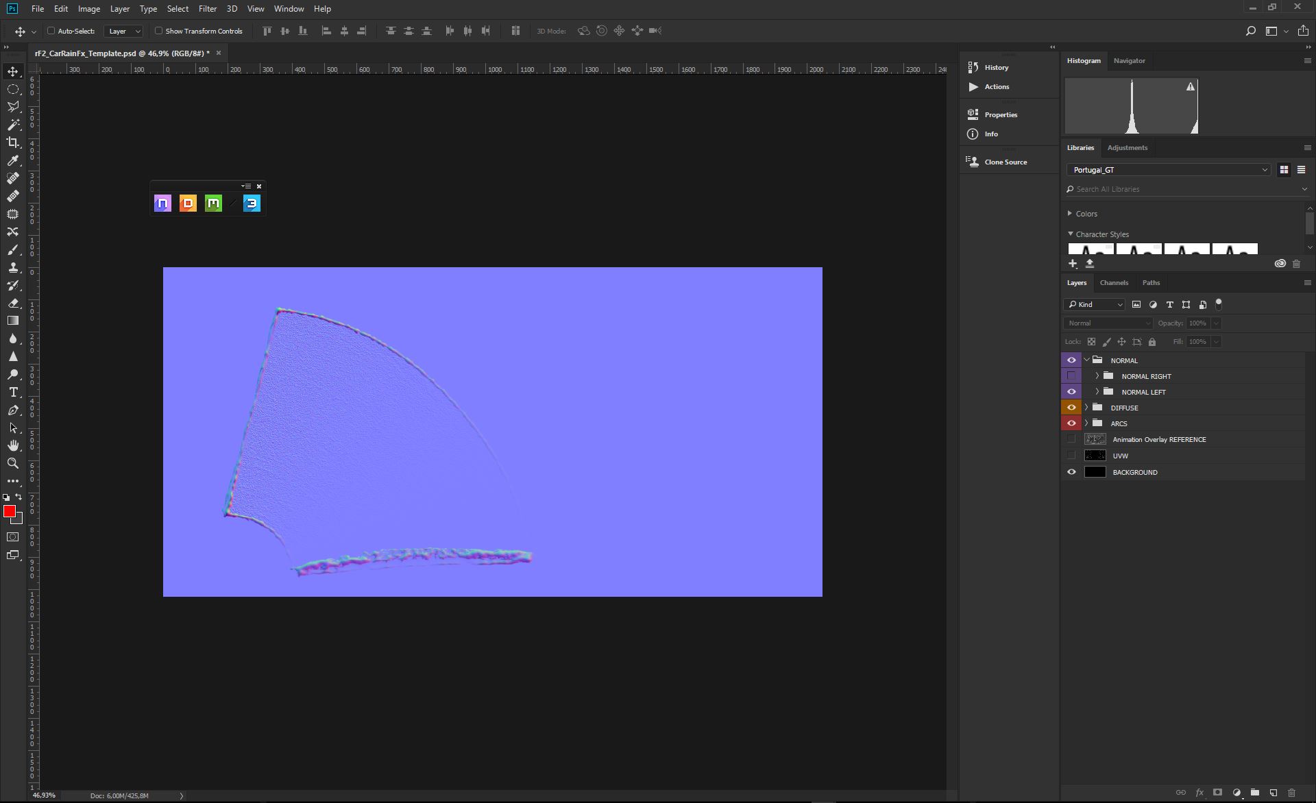
YAY! We are almost done here! Now let's grab a coffee ![]() ...and before to move to the last steps, we like to invest a bit of time to clean up our Template at best, naming all the layers and folders in the stack;
...and before to move to the last steps, we like to invest a bit of time to clean up our Template at best, naming all the layers and folders in the stack;
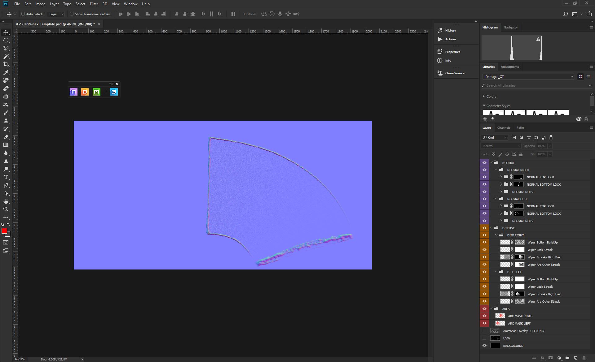
Now you have both Right and Left Normal maps, ready to be saved for the game engine. We need a .PNG format, default settings. Both Normals needs to be saved into the "teams" folder, of the car mod you are working on;
Names for the files are;
- RIGHT Diffuse; veh_wipers_arc_normal_0.png
- LEFT Diffuse; veh_wipers_arc_normal_1.png
PS: if you have just a single wiper system, you save just as "veh_wipers_arc_normal_0.png"

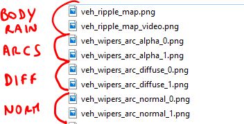
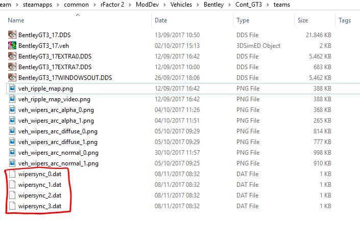
Before to save our .PSD Template, let's be sure we have all these core files, in the car mod "teams" folder. Without these files the system will not work (if we have just 1 Wiper system, we need just one Arc, one Diffuse and one Normal);
It's now time to hit the game engine, loading the car in Mod Dev.
2.9 - Mod Dev - Sync Wipers to Arc Masks
Our last step is to sync our Arc masks, to the wiper animations. To do so, we have a system, in Mod Dev, that does allow us to set and save a number of Key Points, along the animation, to force the Arc Mask to stay in sync with the wiper. This will fine tune the wiper/rain interaction to a perfect match.
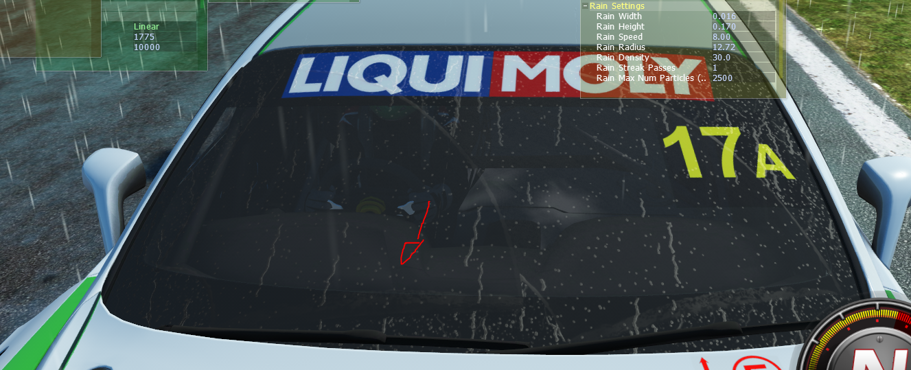
First step is to open the Mod Dev, and set a Practice Session, with Scripted Weather, all set to Overcast % Storm. This is to force the rain to be there for the entire wiper setup session. Of course we also need to load the car we are working with, and that we are sure it has all the maps we just created. We will also pick a track which does load the cars outside the garages, so that we can easily setup our car, without any manouver to leave the garages. Nola is perfect for the goal;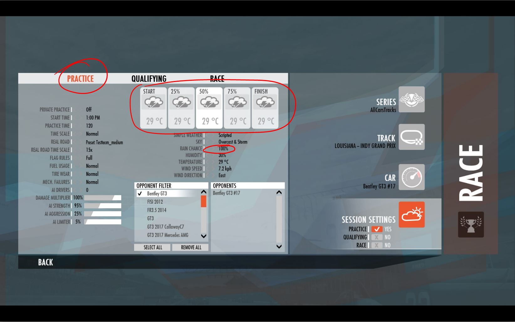
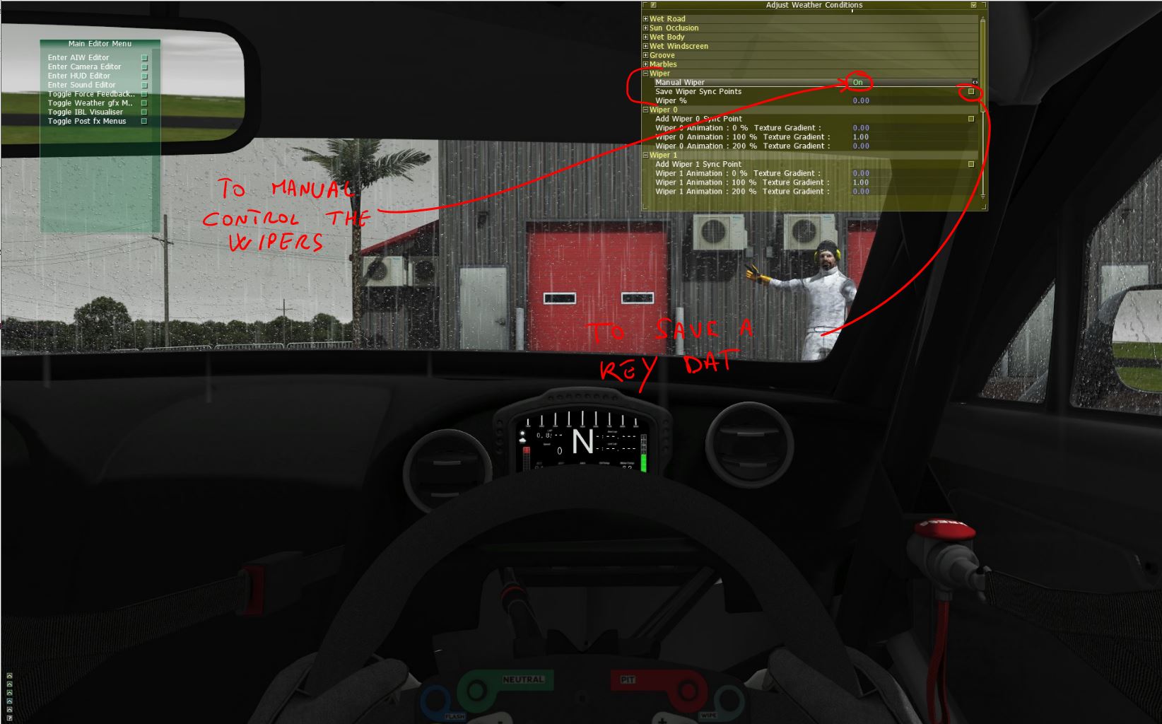
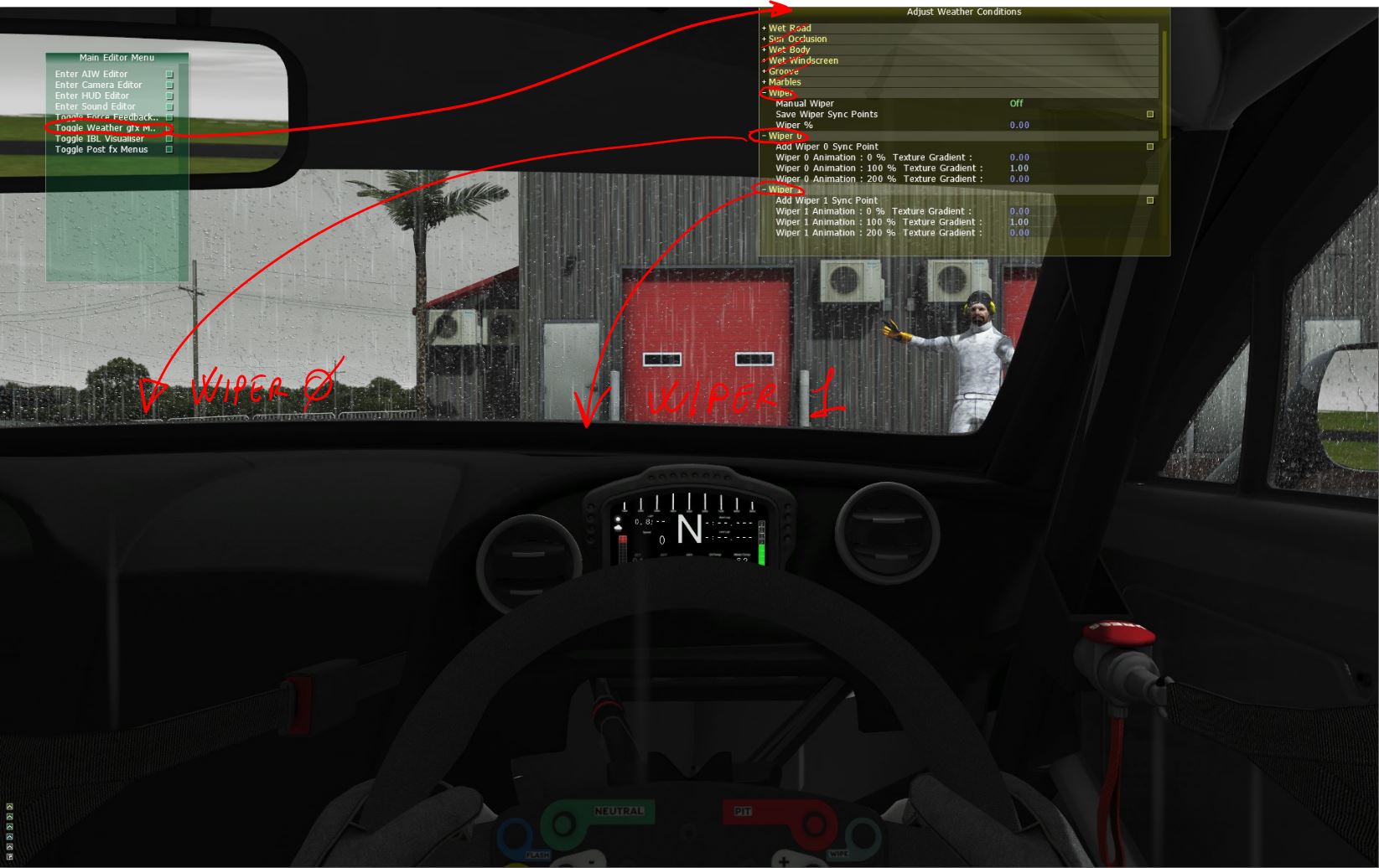
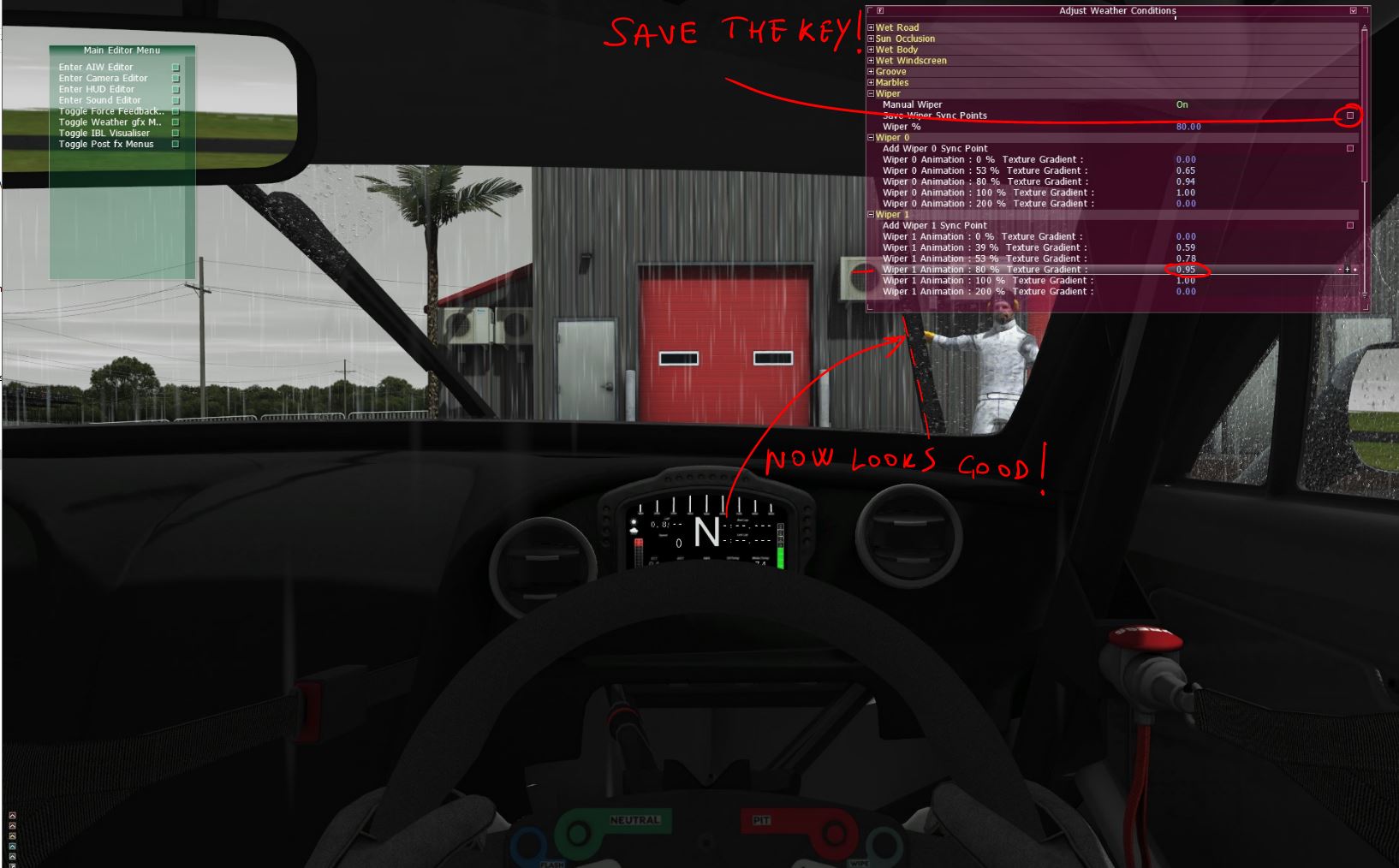
The Editor we need is part of the Weather GFX Menu, so we will open this, and select the Adjust Weather Conditions editor, as in the picture.
The sections of the Editor we are interested for are;
Wiper
- Manual Wiper -------------------------------------→ ON / OFF -----------------------------→ Does switch the manual control of the wiper that we need to check and set the Keys (Sync Points)
- Save Wiper Sync Points -----------------------→ Button ----------------------------------→ Click that button to save the Key into a .dat file, stored in the car "teams" we are working with.
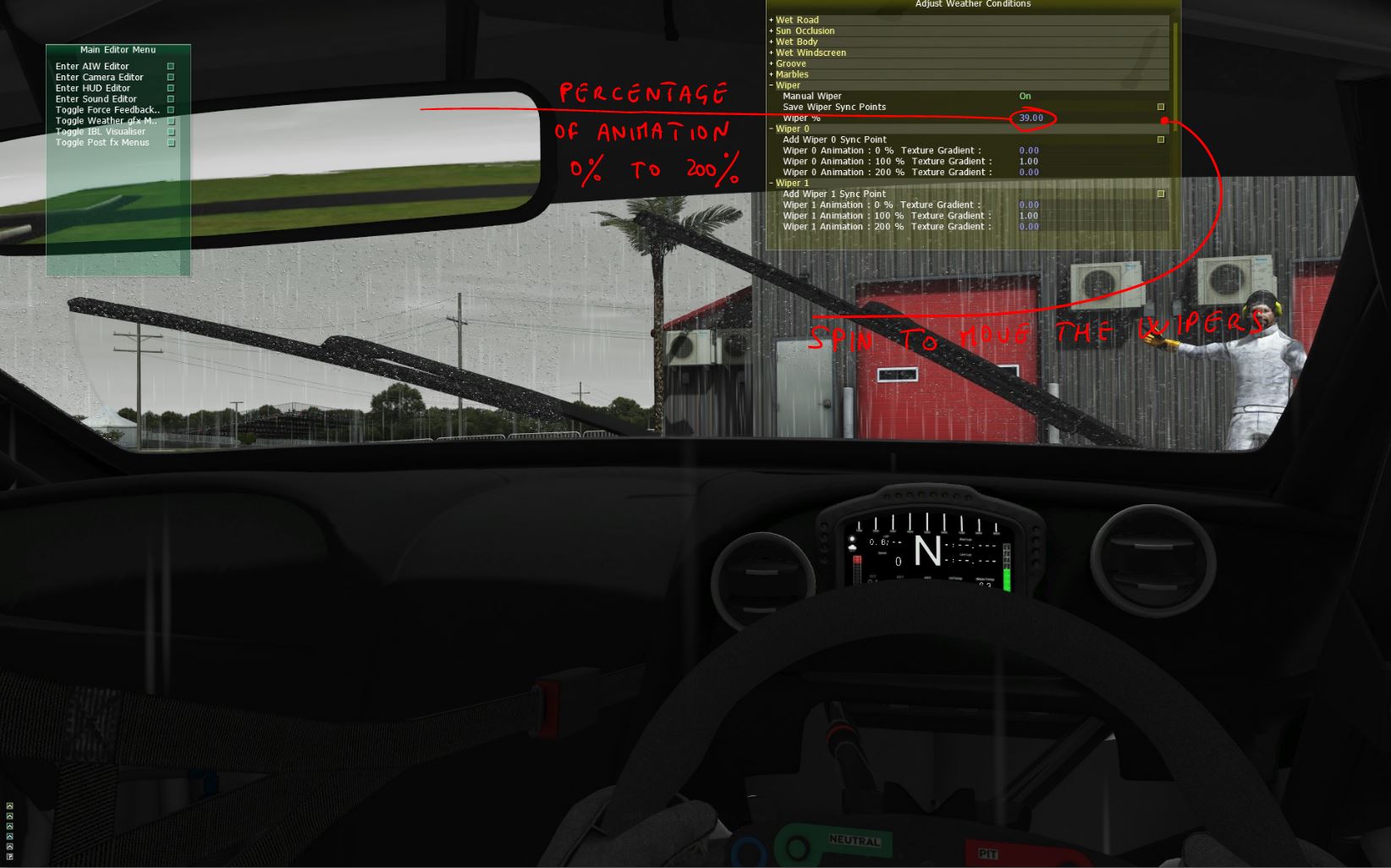
- Wiper % --------------------------------------------→ Spinner + Read Out ------------------------------→ This is a readout from the manual control. It does show the percentage of wiper animation, from 0% to 200% (0% start - 100% lock up - 200% down)
Wiper 0 (Left Wiper)
- Add Wiper 0 Synch Point -----------------------------------→ Button --------------------→ Click this button to add a Key (Synch Point) at the current wiper position, that you read in the Wiper % readout (manual control needs to be ON)
- Wiper 0 Animation : 0% Texture Gradient---------------→ Spinner ------------------→ allow to change the Texture Gradient position (Arc mask), to match the real Wiper position. Value from 0 to 1 (Gradient all down / all up)
- Wiper 0 Animation : 100% Texture Gradient------------→ Spinner ------------------→ allow to change the Texture Gradient position (Arc mask), to match the real Wiper position. Value from 0 to 1 (Gradient all down / all up)
- Wiper 0 Animation : 200% Texture Gradient------------→ Spinner ------------------→ allow to change the Texture Gradient position (Arc mask), to match the real Wiper position. Value from 0 to 1 (Gradient all down / all up)
Wiper 1 (Right Wiper)
- Add Wiper 1 Synch Point--------------------------------.---→ Button --------------------→ Click this button to add a Key (Synch Point) at the current wiper position, that you read in the Wiper % readout (manual control needs to be ON)
- Wiper 1 Animation : 0% Texture Gradient---------------→ Spinner------------------→allow to change the Texture Gradient position (Arc mask), to match the real Wiper position. Value from 0 to 1 (Gradient all down / all up)
- Wiper 1 Animation : 100% Texture Gradient------------→ Spinner -----------------→allow to change the Texture Gradient position (Arc mask), to match the real Wiper position. Value from 0 to 1 (Gradient all down / all up)
- Wiper 1 Animation : 200% Texture Gradient------------→ Spinner -----------------→allow to change the Texture Gradient position (Arc mask), to match the real Wiper position. Value from 0 to 1 (Gradient all down / all up)
At the end of the setup process, in this specific case in the guide, we will end with something like that;
Wiper 0 (Left Wiper)
- Add Wiper 0 Synch Point
- Wiper 0 Animation : 0% Texture Gradient : 0.00
- Wiper 0 Animation : 53% Texture Gradient : 0.65 (new sync point)
- Wiper 0 Animation : 80% Texture Gradient : 0.94 (new sync point)
- Wiper 0 Animation : 100% Texture Gradient : 1.00
- Wiper 0 Animation : 117% Texture Gradient : 0.97 (new sync point)
- Wiper 0 Animation : 140% Texture Gradient : 0.71 (new sync point)
- Wiper 0 Animation : 200% Texture Gradient : 0.00
Wiper 1 (Right Wiper)
- Add Wiper 1 Synch Point
- Wiper 1 Animation : 0% Texture Gradient : 0.00
- Wiper 1 Animation : 39% Texture Gradient : 0.59 (new sync point)
- Wiper 1 Animation : 53% Texture Gradient : 0.78 (new sync point)
- Wiper 1 Animation : 80% Texture Gradient : 0.95 (new sync point)
- Wiper 1 Animation : 100% Texture Gradient : 1.00
- Wiper 1 Animation : 117% Texture Gradient : 0.96 (new sync point)
- Wiper 1 Animation : 140% Texture Gradient : 0.82 (new sync point)
- Wiper 1 Animation : 200% Texture Gradient : 0.00
The setup it's all about moving the wiper, step by step (manual control), while it's raining hard, until we see that there is a big offset between the Arc gradient on the glass and the wiper position. Remember we have single setup per wiper, so we need to check both, at every stage of the wipers animation. This mean that may happen that, at the same point in the animation, we have a wiper in sycn with the Arc gradient, and the other out of synch. This will tell us that we need to add a new Key (Synch Point) for the wiper out of sync, and then manually set the percentage of the texture gradient, so that it will match the wiper position.
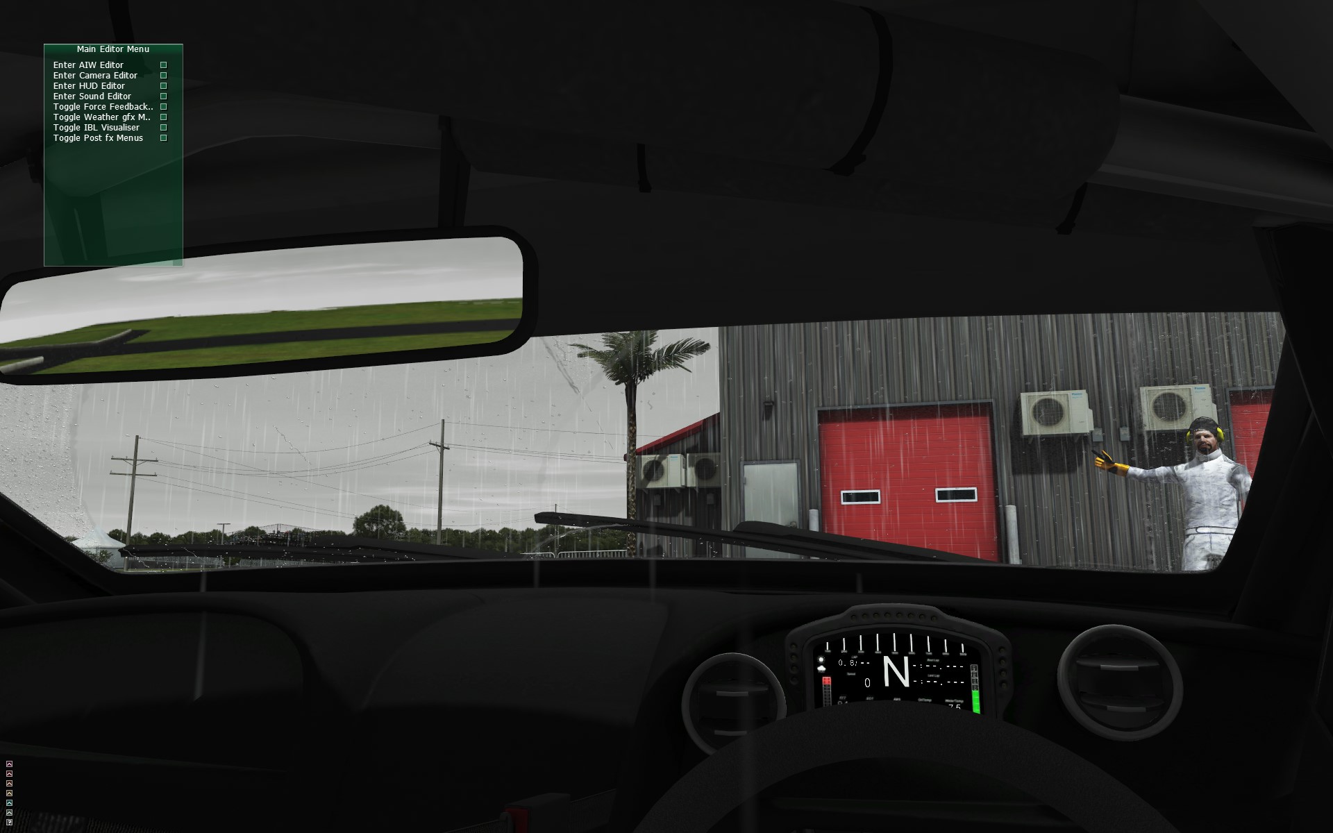
Let's visualize the process;
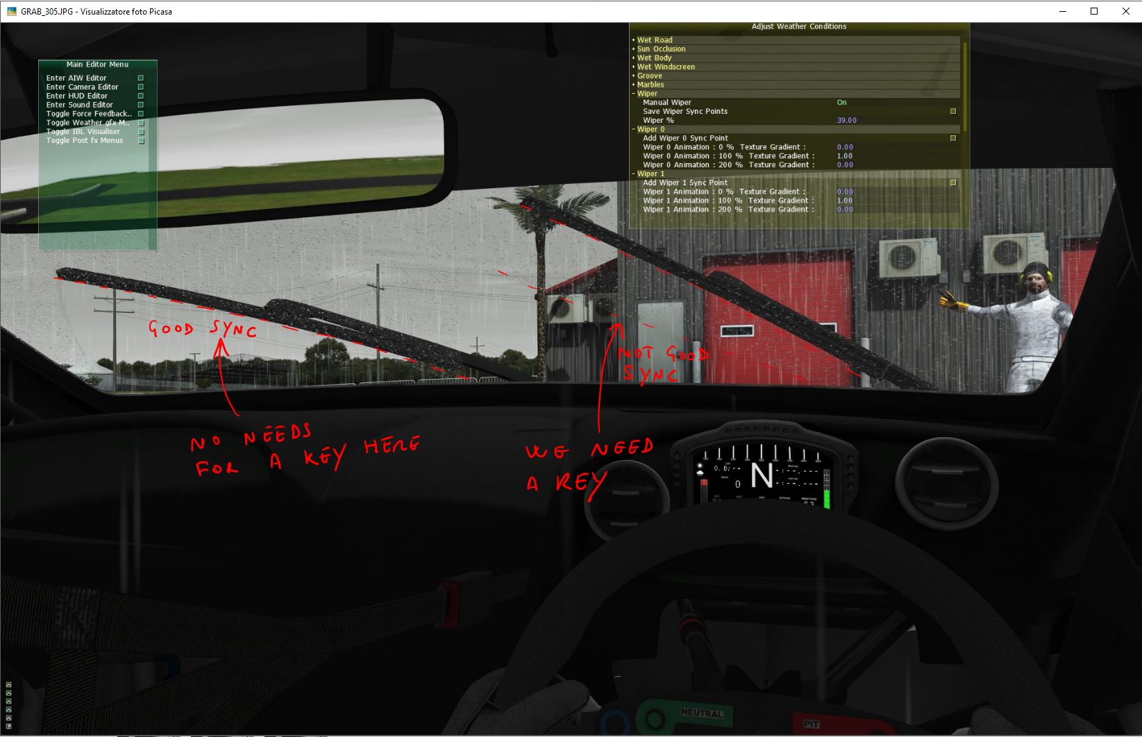
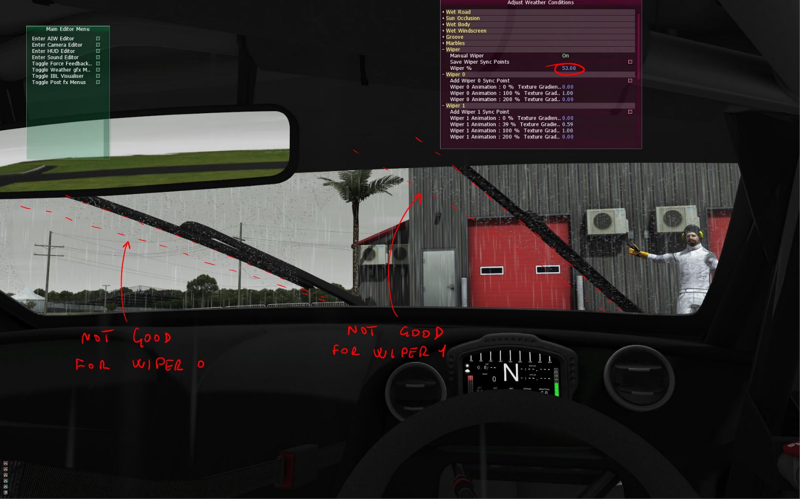
Now we are manually controlling the wipers animation, until we catch that at 39% of the animation, we have a big out of synch on the right Wiper (Wiper 1);
As just stated, we are in a situation where at 39% of the wiper animation, the Wiper 0 still looks in sync, while the Wiper 1 does show we have a big out of sync, so we need a key here!;
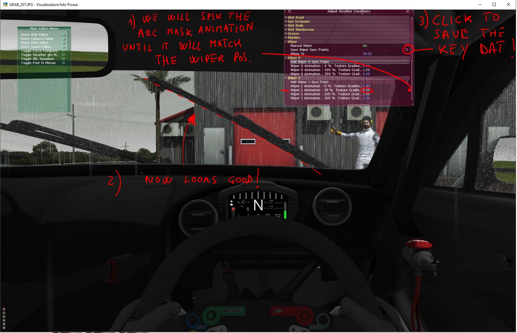
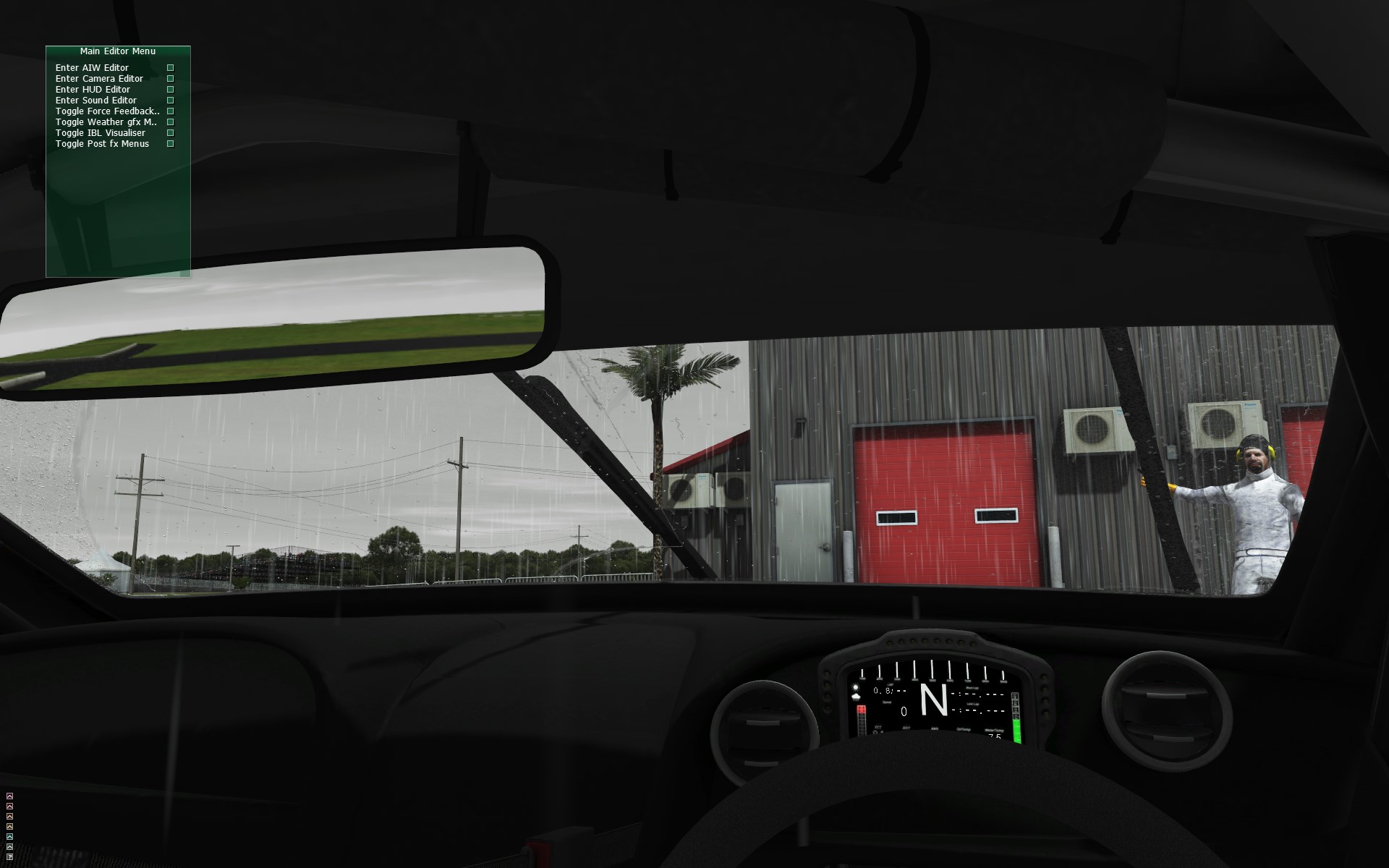
We will click on Add Wiper 1 Synch Point. We'll get a new key in the list, at 39%, where we'll be forcing the Arc texture gradient to move forward until it will match the real wiper position;
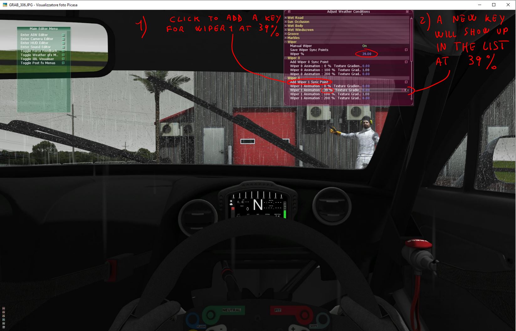
At 39% of the real wiper animation position, we will want the Texture Gradient to be at 0.59, to catch and match the wiper position. Now it's time to save!;
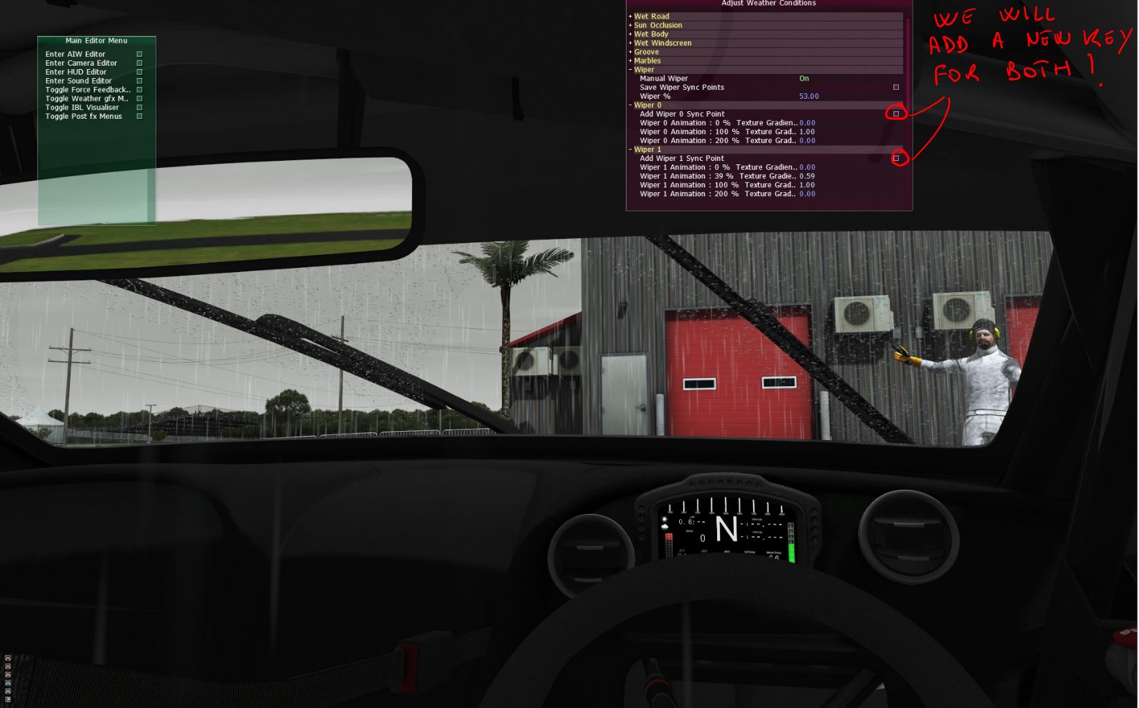
Proceeding with the manual control of the wipers, we catch another out of sync, at around 53% of the real wiper animation;
We'll be now adding 2 keys, because both are out of sync;
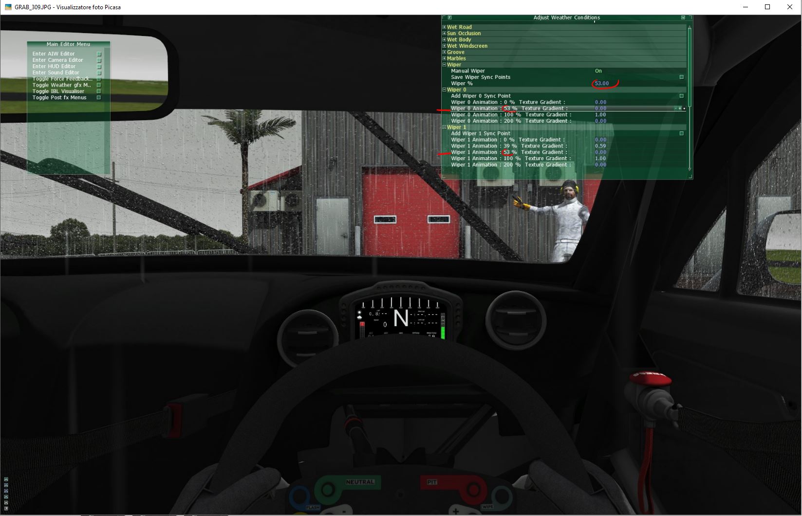
At 53% of the real wiper animation position, we will want the Texture Gradient of the Wiper 0, to be at 0.65, to catch and match the left wiper position. Now it's time to save again!;
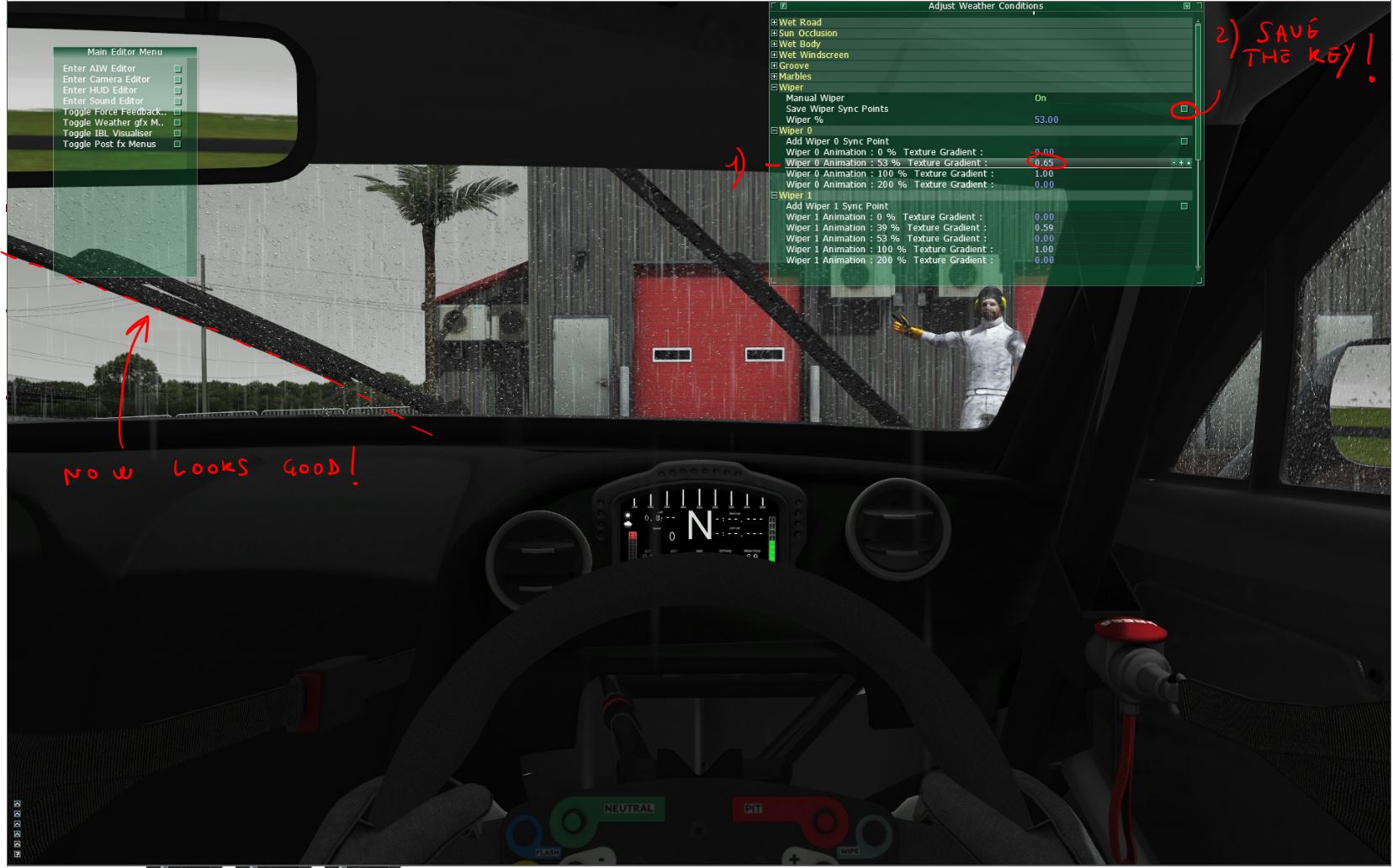
At 53% of the real wiper animation position, we will want the Texture Gradient of the Wiper 1, to be at 0.78, to catch and match the right wiper position. Time to save again!;

Proceeding with the manual control of the wipers, we catch another out of sync, at around 80% of the real wiper animation. Both wipers are again out of sync;
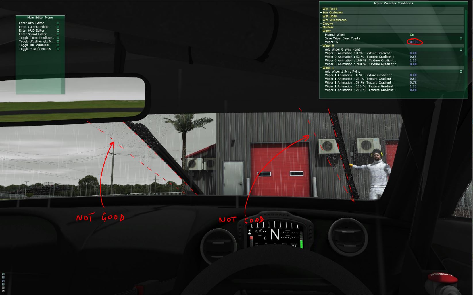
We'll be now adding 2 keys again, because both are out of sync;
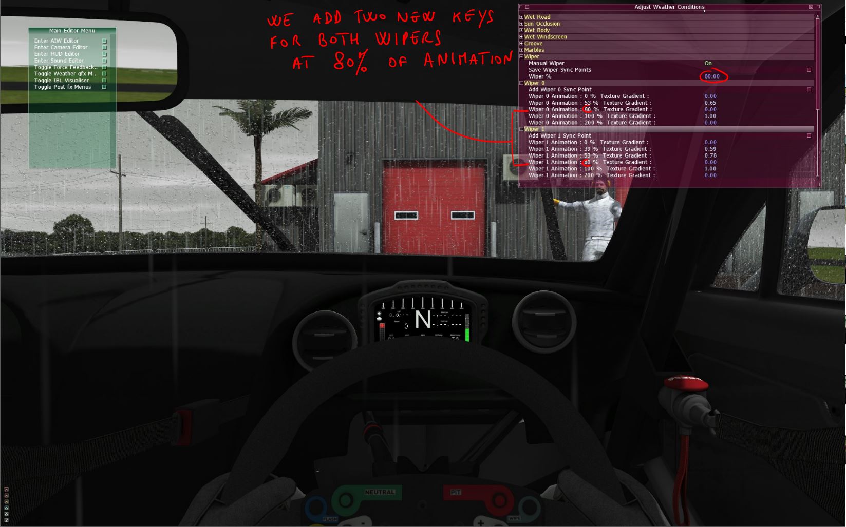
At 80% of the real wiper animation position, we will want the Texture Gradient of the Wiper 0, to be at 0.94, to catch and match the left wiper position. Time to save again!;
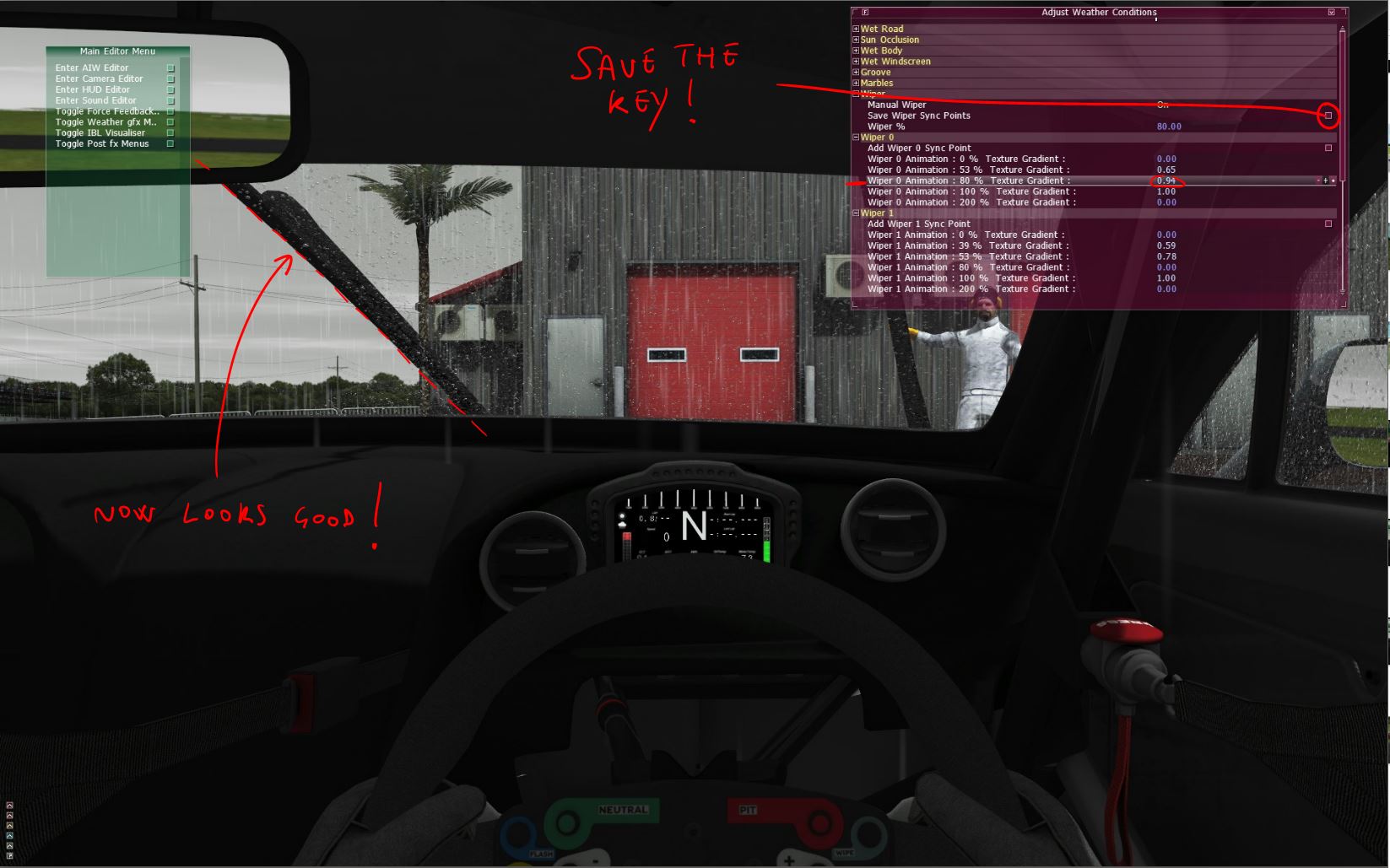
At 80% of the real wiper animation position, we will want the Texture Gradient of the Wiper 1, to be at 0.95, to catch and match the right wiper position. Time to save again!;
After this the wipers are looking in sync for the first part of the animation (forward movement). Now you'll be doing the same procedure while moving the animation for the second part (backward movement). After you set all the keys from 0 to 100% (FW) and from 100% to 200% (BACK), we can turn off the Manual Control, and perss "W" to activate the wipers and check the final result. Be sure you saved everything.
You should now have these files in your car mod "teams" folder;
ADDENDUM; If you have a wiper that does start from the middle of the windscreen, you will need to set your Gradient to average 50% (depend where the wiper is actually parking), at Animation 0%, so that the mask it will start from there.
The Rain Implementation is now done, and with all files in place it will look and work always as its best! ![]()
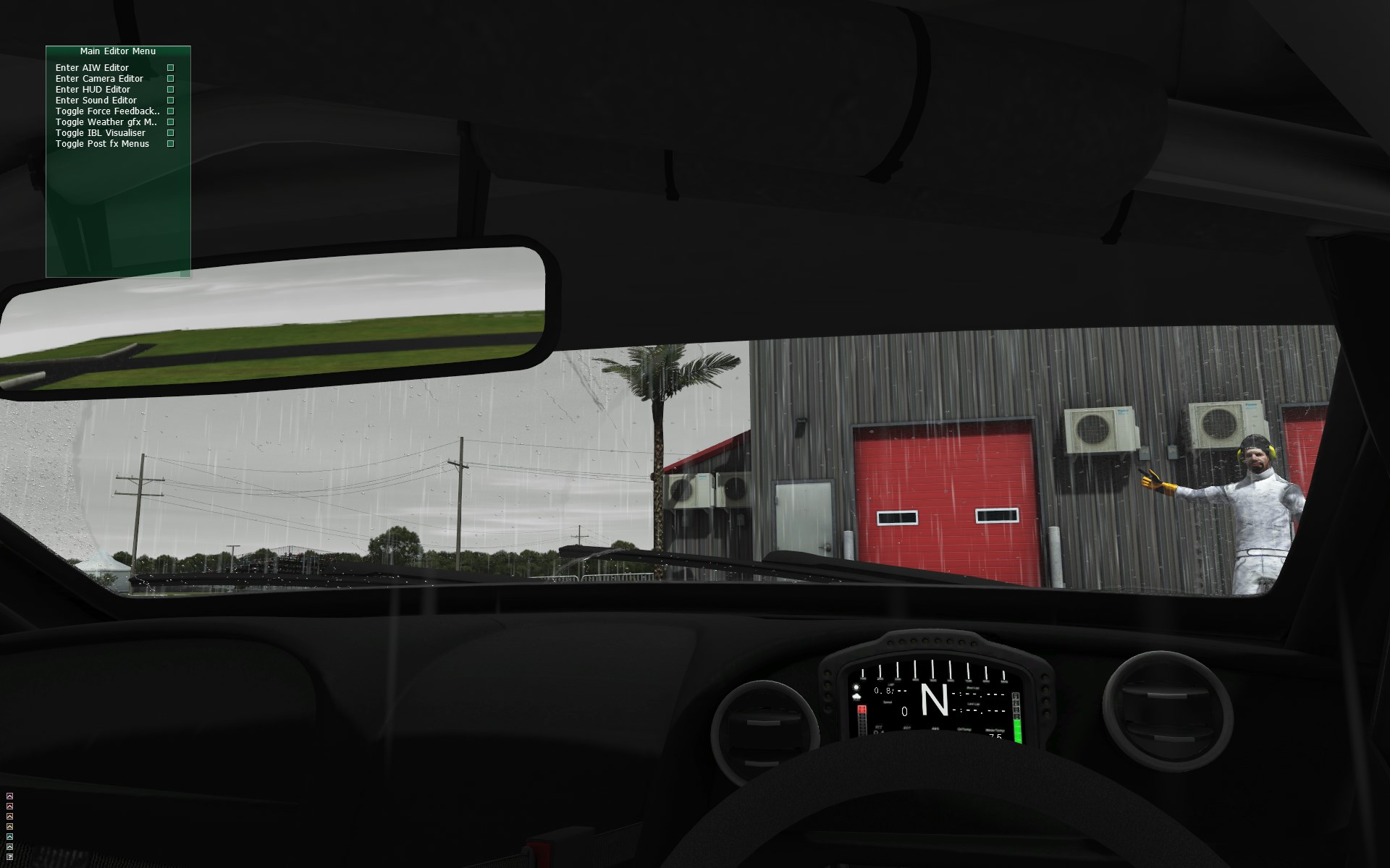
Step 3 - Checklist Ingame
3.1 - Check Ingame
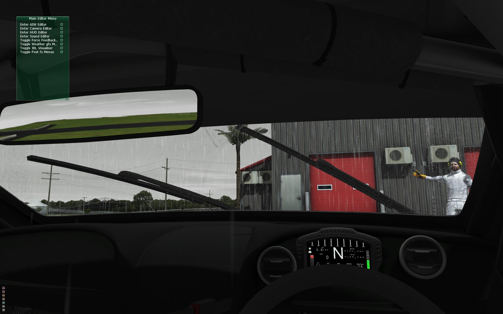
Check that your job is working in all conditions and features;
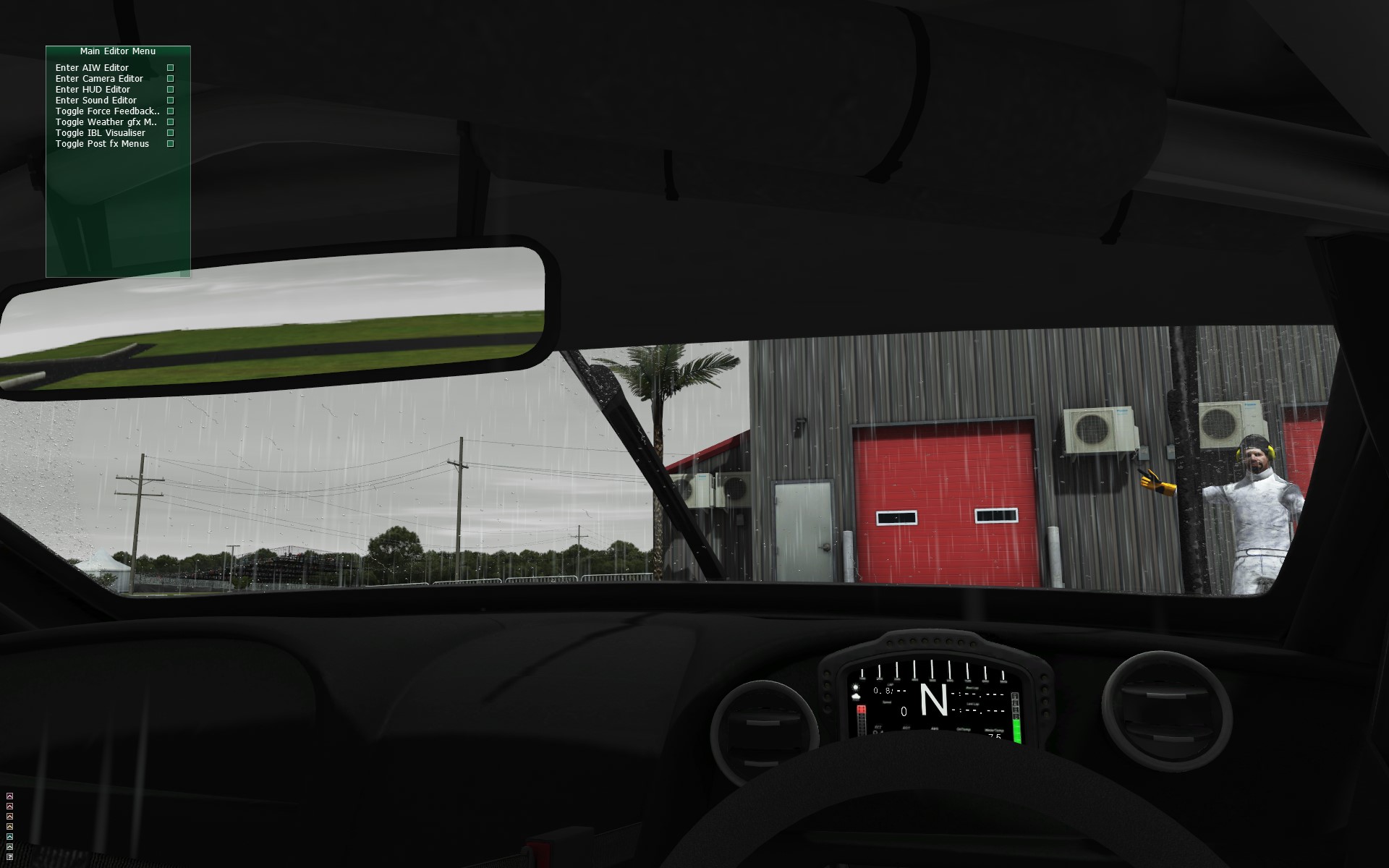
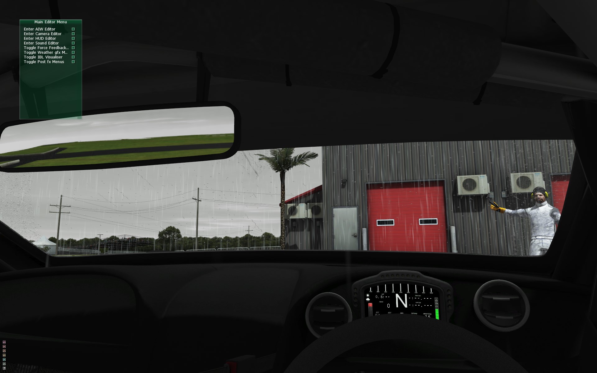
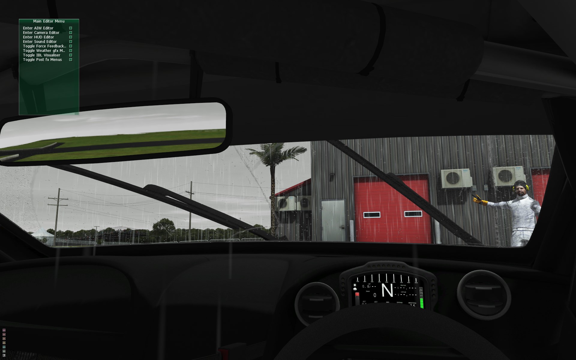
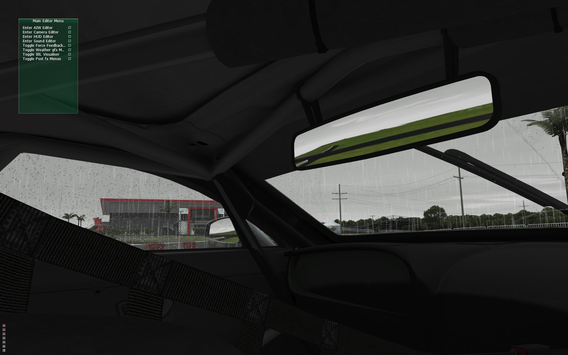
- How it looks in the Windscreen and check the Wiper/Texture Gradient sync
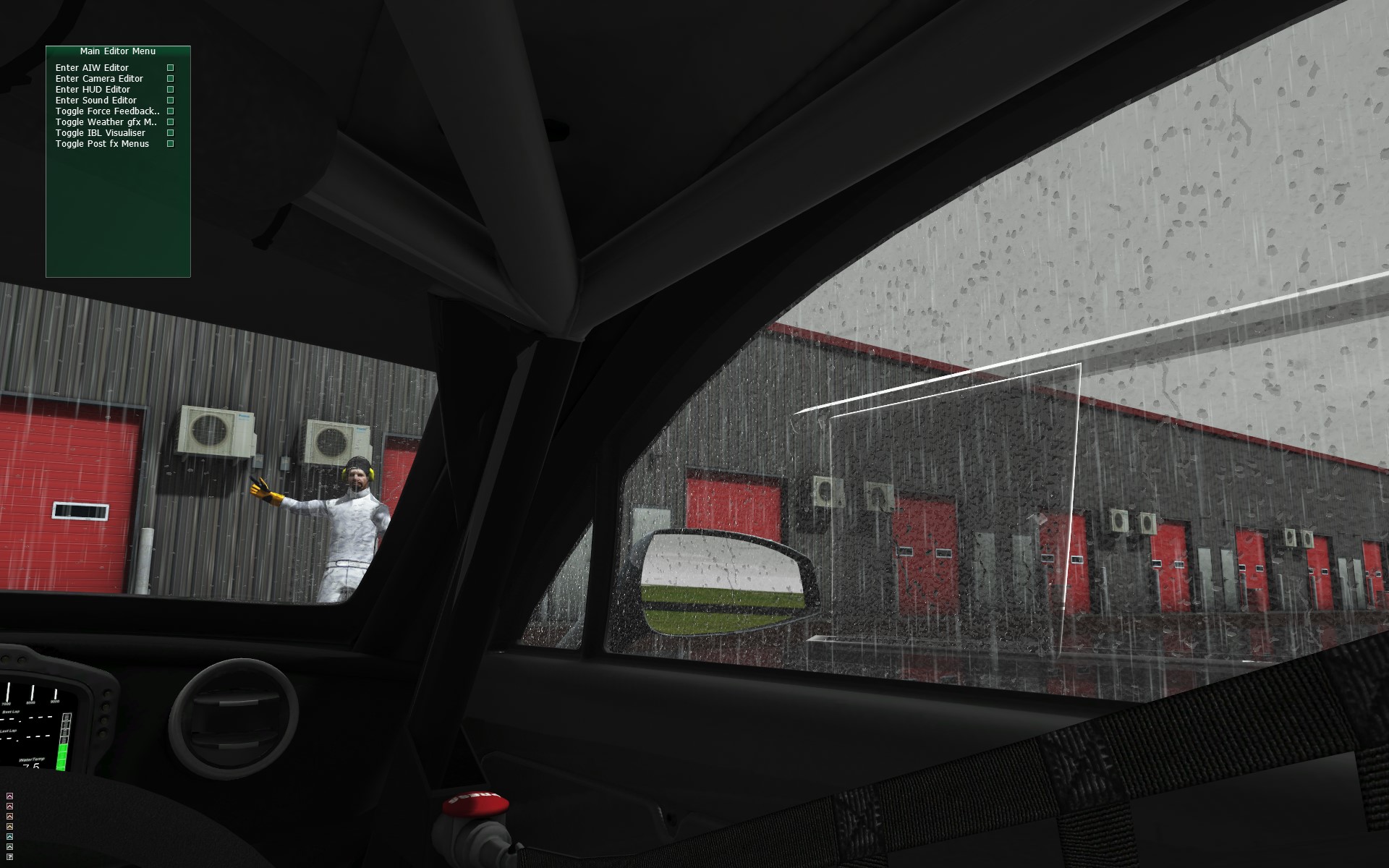
- How it looks on the Left Side Window. Check constancy in the scale
- How it looks on the Right Window. Check constancy in the scale
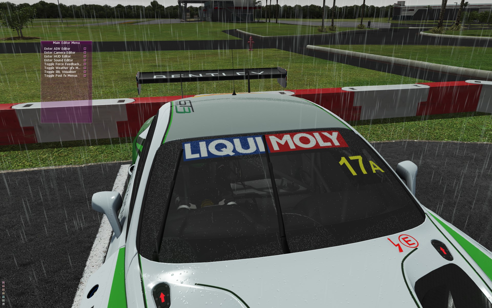
- How it looks from the esterior. Check that it does match the visual experience we had watching from the cockpit.
- Check the rain on the body, when parked and in motion. Check that the streaks are moving the right direction.


3.2 - Art Constency Check
Our reference benchmark car is the Bentley Continental GT3 2017. The same we used in this Guide.
For any further check you can contact your responsible for the Art Direction
How the technology works on the code side
The rain is rendered separately in different 2D textures for Windscreen and body.
Note that the rendering of the rain drops/rain ripples/clear/clear by wipers happen in 2D, with no info about the 3d geometry.
Windscreen
Internally the game renders this render target for the windscreen when it rains:
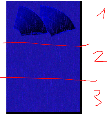
This is a 2048 * 3072 render target.
This is divided in 3 equal sections, each one if it it's 2048 * 1024.
- In Section 1 the rain effect for the front glass is rendered
- In Section 2 the rain effect for the left AND right glass is rendered
- In Section 3 the rain effect for the back glass is rendered.
For the artist Section 3 can be considered not existant. I added it as a special case because we can do optimisations here.
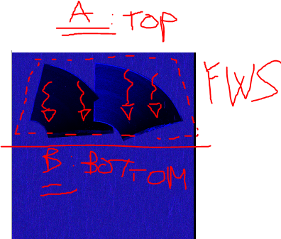
So the artist should only considering the following:
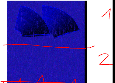
This is a 2K * 2K texture.
We need to map the upper part of the texture (section 1) to the windscreen.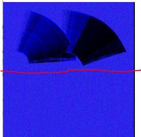
Note : i am drawing the rain effect on this 2D texture, therefore in order for the ripples to move in the proper direction,
We need to map the windscreen in a way that "respects gravity".
I am drawing the ripples in the textures from top to bottom, therefore the windscreen UV should respect that.
In other words the windscreen 3D object bottom part must be mapped on the bottom side of the dotted rectangle (B),
viceversa for the for the topmost part.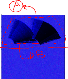
When the car is stationary we have a ripple effect going on. Those are supposed to be raindrops that accumulate and they fall down due to gravity.
If you followed the previous mapping when the car is not moving they should fall following the gravity, as expected.
Note again that i'm drawing on a 2D plane so it's vital that the windscreen is mapped correctly.
If the windscreen is mapped upside down you'll see ripples go upwards instead of down.
There is no "magic" involved in changing directions of the ripples: it's content drive from the artist's UV mapping of the windscreen.
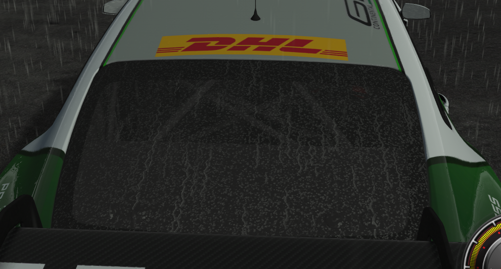
This should generate the following:
0 Mph: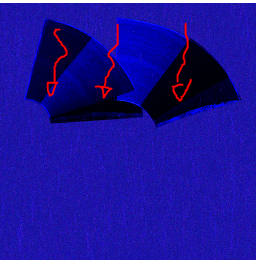
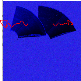
When the car is moving the ripple angle change depending on the vehicle speed:
75 Mph speed: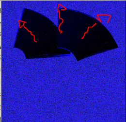
The transformations are handled in code, you just need to make sure that when the car is moving the rain ripples are pointing outwards the center of the windscreen. It should NEVER happen that the ripples go to the center of the screen.
The angle of the ripples change depending on the speed of the vehicle:
30 Mph speed:
15 Mph :
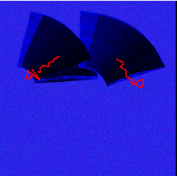
But again, for any circumstance they should never point INWARDS
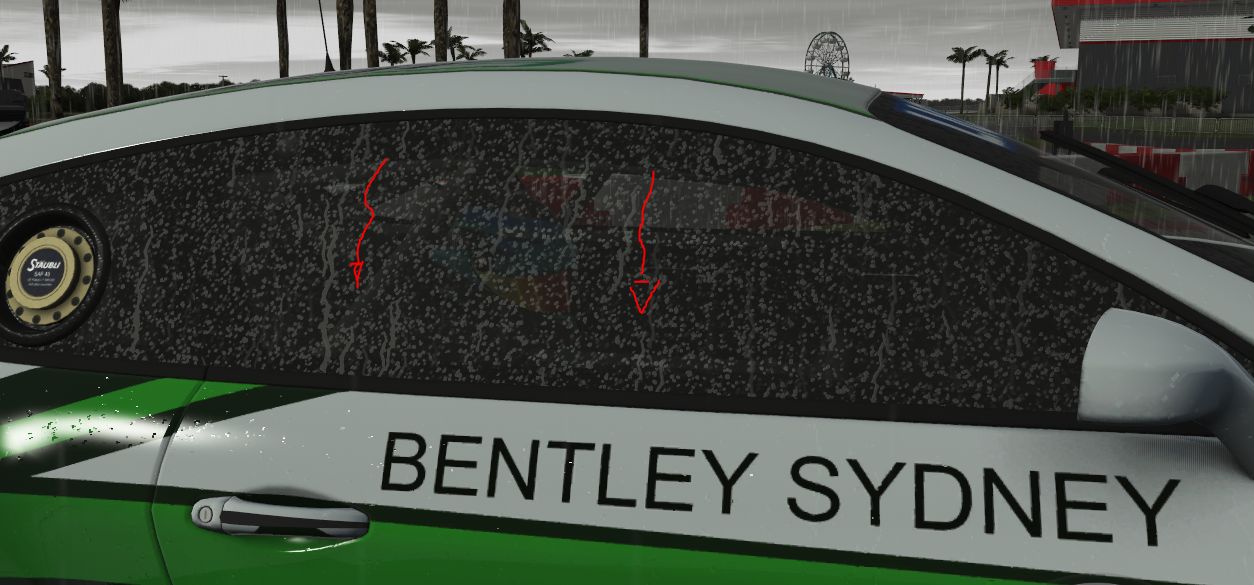
We need to map the lower part of the texture (section 2) to the left, right screen.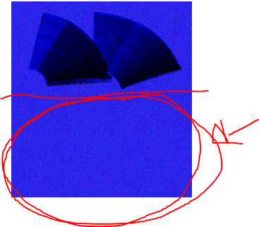
Initially i though that we could have the Left and right screen mapped with the UV flipped horizontally,
since that was complicated to make, the Left and right screen can have the same UV mapping for the rain texture.
In order to achieve this, i am manually flipping the U coordinate in the shader, so the artist doesn't have to.
Of course in order to do that i need some info that tells me which windscreen i am currently rendering in the shader.
The info of which windscreen i am rendering comes from the vertex color setting previously discussed
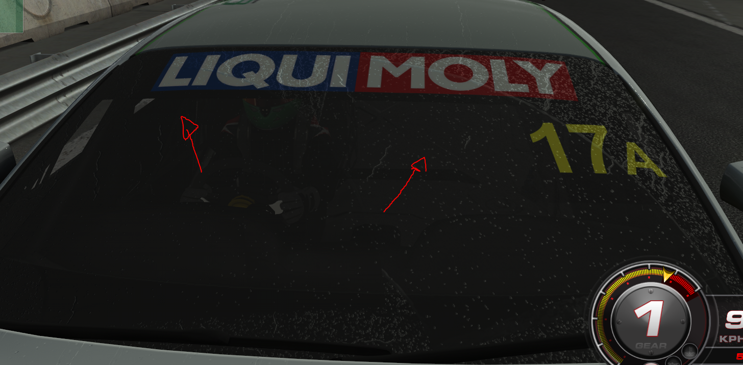
Left : (arrow is pointing to the front windscreen)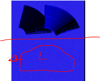
Right : (arrow is pointing to the front windscreen)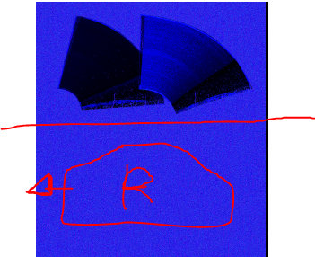
Again since i am rendering the rain ripples animation on this texture it is vital that they are mapped correctly.
0 Mph: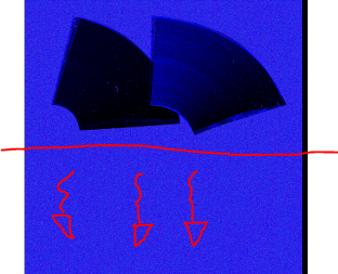
At zero speed they should fall, following the gravity.
If they're going upwards there's something wrong with the UV mapping.
75 Mph: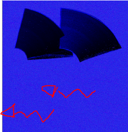
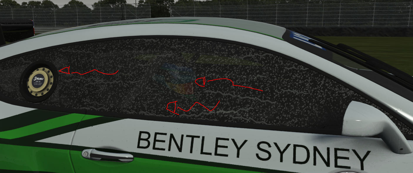
At higher speed the angle is changed, i am handling the animation in code, just make sure that the rain ripples both in LEFT and RIGHT screen are going to the back of the car.
If they're not there's something wrong with UV mapping.
We need to map Section 2 again to the Back screen: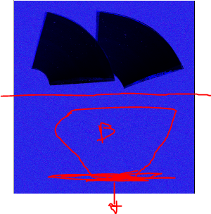
The back screen shares the same section of the rain texture of the Left and right screen.
(internally this is not true, but it has been exposed like this to the artist to make things simpler).
Just make sure that the bottom of the 3d object is mapped at the bottom of the texture (same stuff as the front windscreen).
When animating the rain ripples should always go from top to bottom no matter the speed of the car (the speed only increases their number).