Animations for Wipers and other things
Table of Contents
Generally speaking, all animations in rFactor 2 are set up in the same way; so, this document can be used as a basic animation guide. However, the point of this document is to focus specifically on the new windshield wipers. They really are not too difficult as long as you remember a few key items with regards to set up. With that, let’s get started.
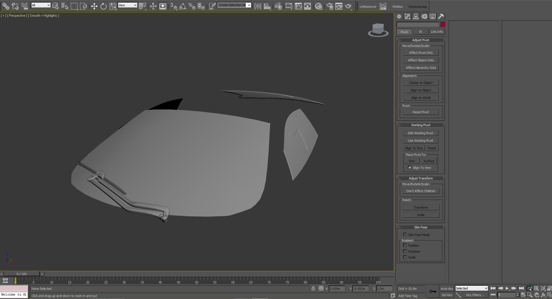
Image 1
As shown in the shot above, for the sake of clarity I’ve pulled both the windshield and the wiper objects into a new MAX scene. The scene is using the standard unit setting (1 unit = 1 meters); and the objects are in their original positions. While you don’t have to do this, I prefer to animate in small, efficient scenes using only the assets that the animation requires.
Set-up and Prerequisites
There are a few basic items you want to be sure of regarding the wiper itself before you try to animate. If any of these are not addressed now, they will most-certainly affect the rigging of the wiper, and consequently the final exported object and animation.
First, you need to make CERTAIN that the wiper is all one object. If it isn’t, you’ll need to attach all the various parts that make up the wiper into one complete object, similar to what is shown below in Image 2:
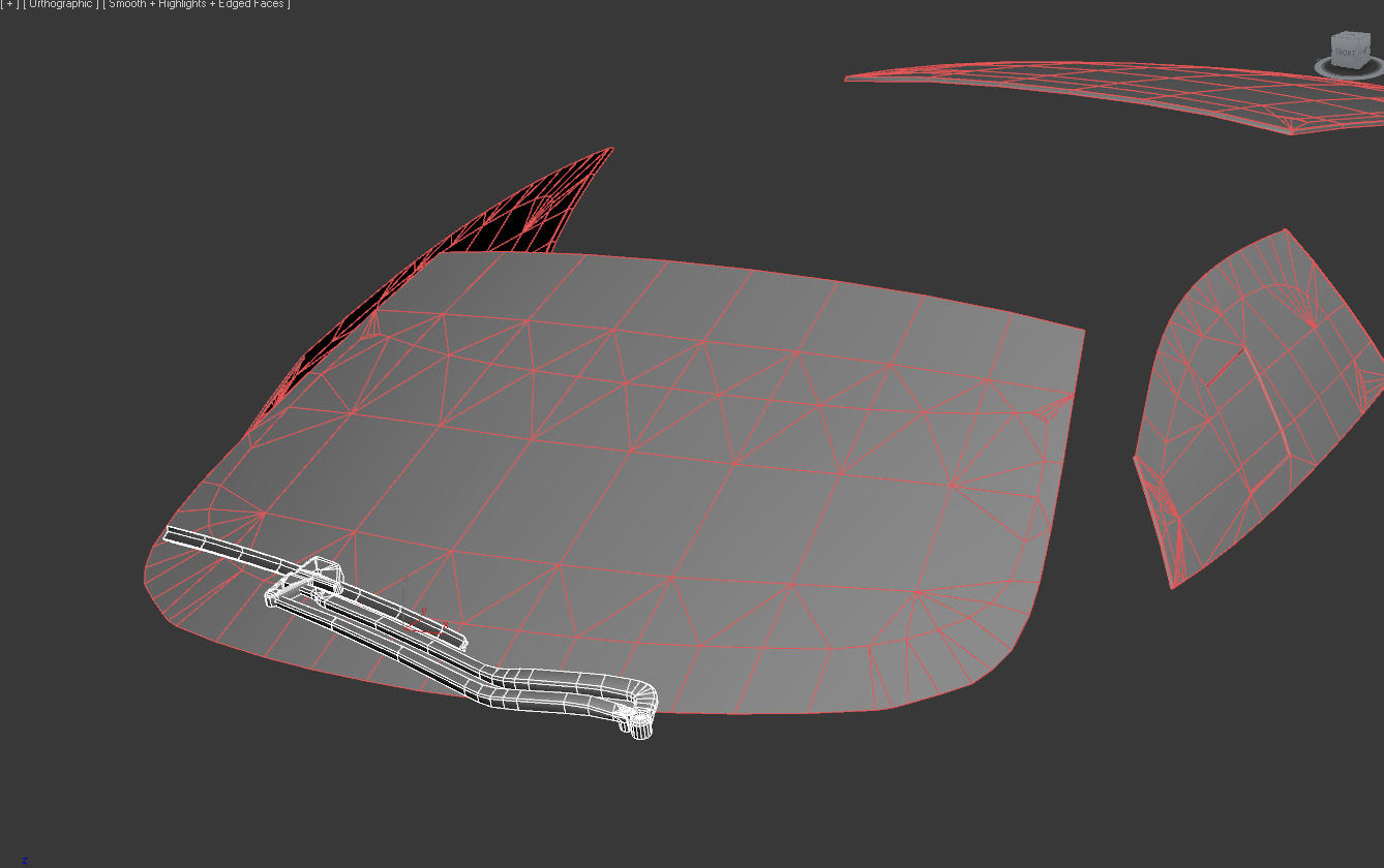
Image 2
As you can see, all the parts that make up the wiper--the arm, hinges and blade, are joined together as one object. Also, the wiper should be in its “at-rest” position, making sure that the blade rests just above the windshield without penetrating it. Image 3 demonstrates this--showing the “inside” of the windshield. Again, note that the wiper blade does not penetrate (or “clip through”) it:
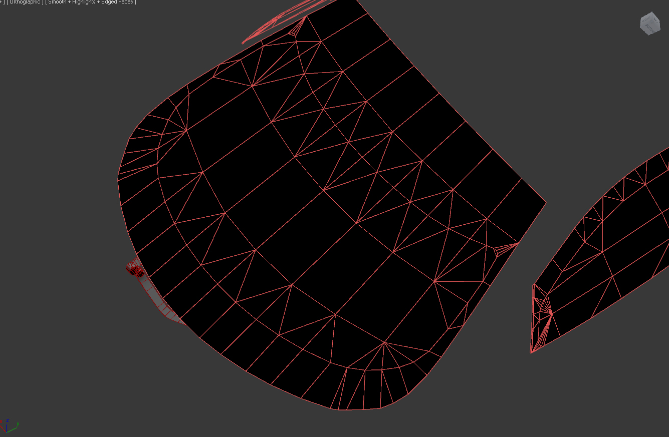
Image 3
Next, if you’re animating a car part, as we are here, you’ll want to be sure that the wiper’s pivot point is at world 0.0, 0.0, 0.0. With the wiper selected, click on the Hierarchy tab and, within “Adjust Pivot”, select “Affect Pivot Only”
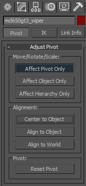
Image 4
Now, right-click on the “Select and Move” tool to bring up the “Move Transform Type-In” tool, as shown in Image 5. This tool allows you to precisely change the rotation/position/scale of an object.
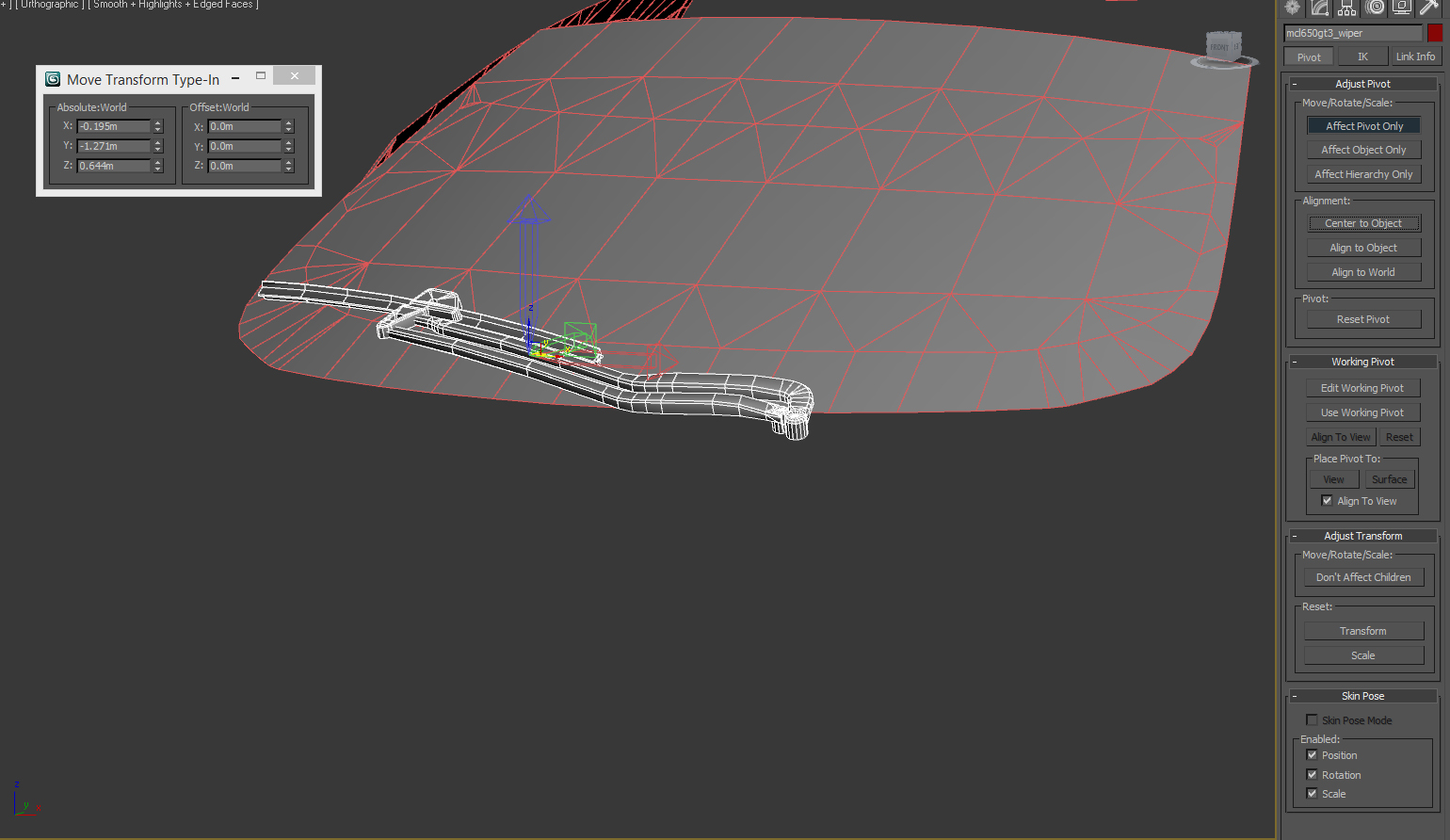
Image 5
Next, right-click on the Absolute:World Up/Down arrows (for x, y AND z) to reset the values to 0.0. Once done, as shown in Image 6, the wiper’s pivot point should now be at world 0.0, 0.0, 0.0. Now, deselect “Affect Pivot Only” (again, in Hierarchy/Adjust Pivot) to get out of this mode.
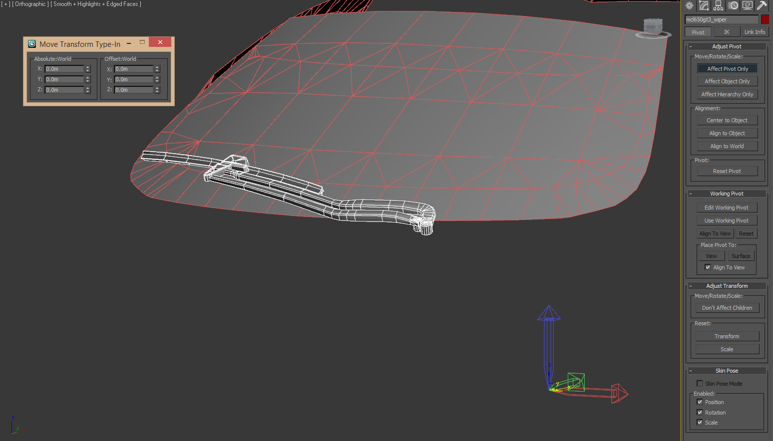
Image 6
At this point, you want to reset all transforms for the wiper. To do this, select the “Utilities” tab and click “Reset XForm” from the Utilities list (NOTE: you may have to click “More…” and find it in the list there if you’ve not set up a button for it). Once you’ve done this (as shown below in Image 7), with the wiper object still selected, simply click on the “Reset Selected” button.
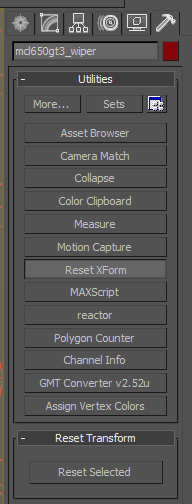
Image 7
If you navigate back to the “Modify” tab, with the wiper selected, you should now see a “XForm” modifier in the object’s stack. Go ahead and collapse the modifier stack by right-clicking on the “XForm” modifier and selecting “Collapse To” from the menu (Image 8).
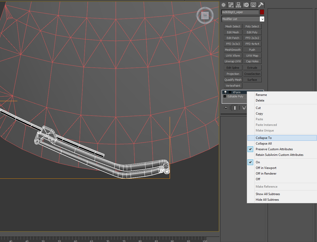
Image 8
Creating the Rig
You should now only have an “Editable Poly” base modifier (or “Editable Mesh” if your wiper was a mesh object). You are now ready to create bones (your “rig”) so the wiper can be “skinned” to them.
The “hardest” part of bone creation is moving them into position where they need to be, and then properly orienting each one so that each will affect the object properly. The number of bones, and the bones’ position/orientation, will vary from one object to the next; but a general rule of thumb (for wipers at least) will be three bones:
The first bone will be located at the wiper’s pivot point (the “Root”).
The second bone will act as the the hinge for the wiper arm. This will allow it to sweep the blade across the windshield.
Finally, the third bone will act as the hinge for the wiper blade, so that it can stay oriented to the windshield as it sweeps over it.
Obviously, more bones can give you more mobility and flexibility when animating. However, additional bones require more resources during playback, so keep the count as low as possible and only add more if you ABSOLUTELY need to. With that, let’s go over the setup of the very basic, 3-bone rig.
To create a bone, select the “Create” tab, and then the “Systems” sub-group. In “Object Type”, press the “Bones” button. In “Bone Objects”, a width and height value of 0.03 is generally pretty good. See image 9:
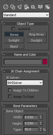
Image 9
Now, using a top-down view, and with the wiper selected, left-click as close to the wiper’s pivot point as possible and drag out a new bone, facing down. Click again to complete the bone. When you do, a second bone will be started. You can right-click to end bone creation. When done, it should look similar to this:
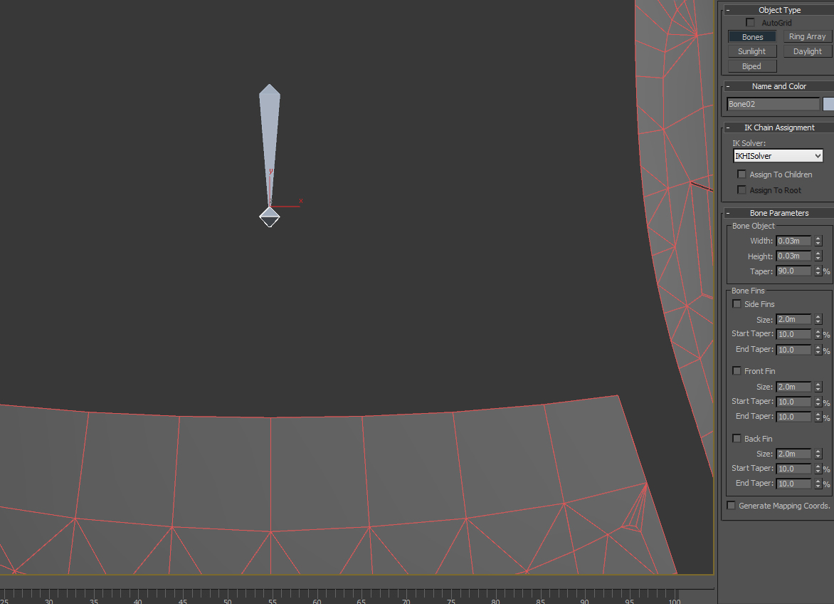
Image 10
You’ll want to delete the erroneous “Bone 2”--simply hit the DEL key with “Bone 2” still selected. It’s good practice to uniquely name the bones for the object. Since I’m demonstrating with the wiper for the McLaren 650 GT3, I’ll name this first bone “mcl650gt3_WIPER_ROOT”.
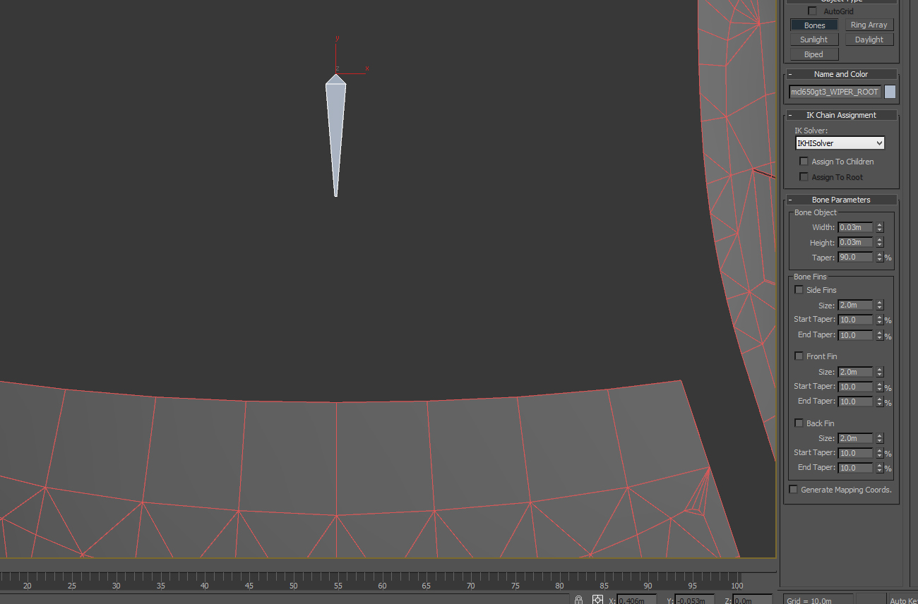
Image 11
Now, for the second bone for the wiper arm. I’ll explain everything, and then provide a visual showing how it should look when finished. Still in top-down, focus the view so you have a good close-up of the complete wiper arm. Again, click the “Bones” button in the Create tab. Now, to begin creating the bone, click on the point where you think the hinge would be that would allow the arm to sweep back and forth. Then, drag the bone out in the general direction of the arm. It doesn’t have to extend out the full length of the arm, but it should be fairly close. Click again to create the bone, and then right-click to cancel bone creation (don’t forget to delete the erroneous end bone that gets created when you do). You should have something similar to Image 12:
Image 12
Now, you’ll need to switch to a side view so you can move the arm bone (which I renamed to “mcl650gt3_WIPER_BONE01”) up to the wiper arm. Once there, you’ll want to rotate the bone and move the bone (using the “Local” “Reference Coordinate System”) so that it is orientated with the alignment of the wiper arm pivot, and with the general orientation of the arm itself. You’ll need to rotate the view around the wiper arm, making tweaks and adjustments as you go. It takes a bit of practice; but once you do it a few times it’s easy to do. When finished, your bone #2 should resemble mine, shown in Image 13:
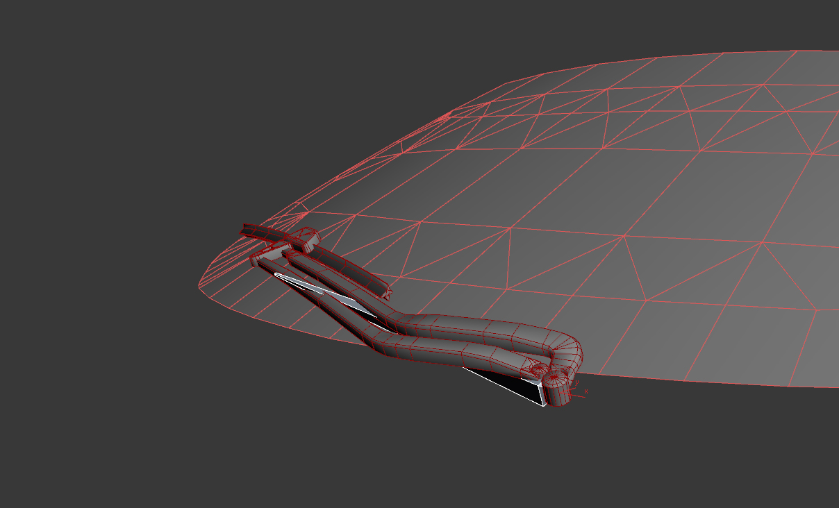
Image 13
You’re going to set up the bone (which I’ll name “mcl650gt3_WIPER_BONE02”) for the wiper blade. This time, you should create it at the hinge where the blade connects to the arm, and then stretch it out towards the outside end of the blade. Click to create the bone, cancel bone creation, and delete the created end-bone. Again, use “local” rotation and move to align the bone with the wiper blade. When done, it should look similar to this:
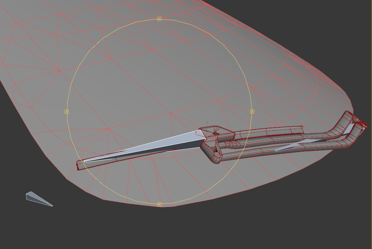
Image 14
You’re now going to chain-link the bones together. Before doing so though, make sure the bones are where you want them. If you need to make changes later, you’ll have to unlink the bones, make the adjustments, and then link them back together. If already skinned, then you’ll also need to redo the skinning, too. That said, linking the bones is easy to do.
Click on the “Select and Link” tool to make it active. Click-hold on the bone for the wiper blade to select it. With the mouse button held, drag the link-line over the bone for the wiper arm. When you release the mouse button the blade bone will be linked as a “child” to the arm bone (the “parent”). Like this:
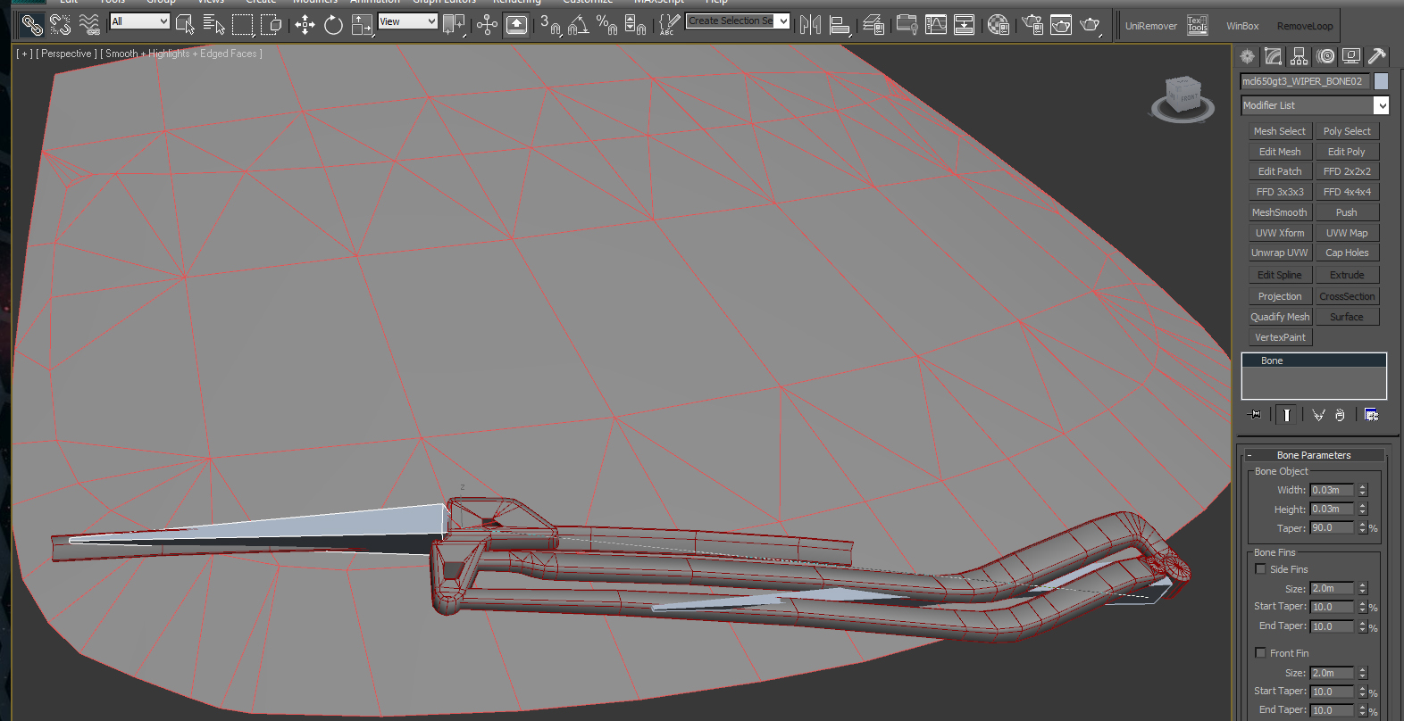
Image 15
You’ll know this worked because both bones will be momentarily selected. When done, select the arm bone, and drag the link line out to the root bone. Again, both bones will be momentarily selected when the connection is made.
You can double-check the connections easily. For example, if you double-click on the root bone, both the arm and the blade bones will be auto-selected as they are both children of the root. If you double-click on the arm bone then the blade will be auto-selected. Assuming all your connections are correct, you’re ready to “skin” the bone rig to the wiper object using a Skin modifier.
Select the wiper object, and then click the “Modify” tab. Add a “Skin” modifier to the wiper object. You’ll need to first add the bones to the modifier. Above the empty “Bones:” list is an “Add” button. Click that, and then select the three bones you created. NOTE: ANY object can be used as a bone, so be sure you ONLY add anything but the bones, as in Image 16:
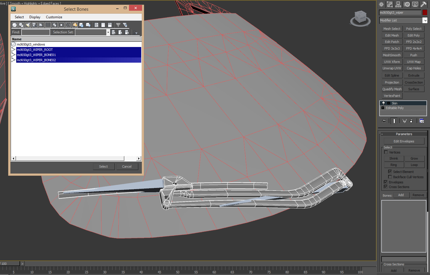
Image 16
Weighting
With the bones added, you’re now ready to “weight” the object’s vertices to them. This is what allows the object to bend and move properly with the bones. I won’t lie, weighting can be time consuming and tedious, especially with organic objects (people, animals, etc). However, it’s also EXTREMELY important to get right. The good news is that, as is the case with wiper, mechanical objects are MUCH easier to do. In fact, most of the time the weighting is binary--either “on” or “off” for each bone.
Each bone will try to weight vertices near it based on its cross-section, distributing weight from one bone to the next. We’re going to be manually assigning weights based on different parts of the object. To start with, we’re going to assign ALL the wiper object vertices to the arm bone. This will assure that we don’t miss any. Then, we’ll assign the vertices that make up the wiper blade to the blade bone. Let’s get started.
Click the “Edit Envelopes” button in the Skin Modifier. We’re going to be working with the vertices directly, so check the “Vectices” check box. Also, uncheck “Envelopes” and “Cross Sections”. Finally, select the wiper arm bone (what I called “mcl650gt3_WIPER_BONE01”). You should see much of the wiper turns red. Your scene should look similar to this:
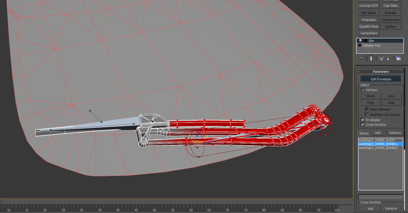
Image 17
Now, we want to select ALL the wiper object vertices (also shown in Image 17). Once done, in the “Weight Properties” section of the Skin modifier, enter a value of 1.0 into the “Abs. Effect:” (stands for Absolute Effect) text field, and press enter. The entire wiper object should turn red (Image 18). Again, this means that ALL of the vertices are now assigned to “arm” bone 01.
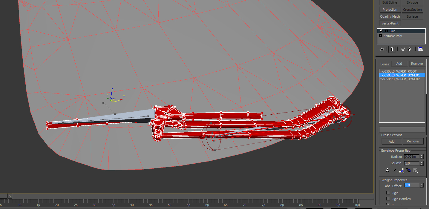
Image 18
Now, we’re going to assign the vertices that make of the blade to “blade” bone 02. I’ll also quickly demonstrate blended weighting when we do. You need to select bone 02 (“mcl650gt3_WIPER_BONE02”). Also, if your wiper blade is a separate element (as the one I’m demonstrating is) you can check “Select Element” in the “Select” section of the Skin modifier. This will let you easily select vertices by element (and you can CTRL-click to select multiple elements).
However you need to do it, select all the vertices required, and enter a value of 0.5 into the “Abs. Effect:” field. When you do, you’ll see the vertices turn orange, as shown below:
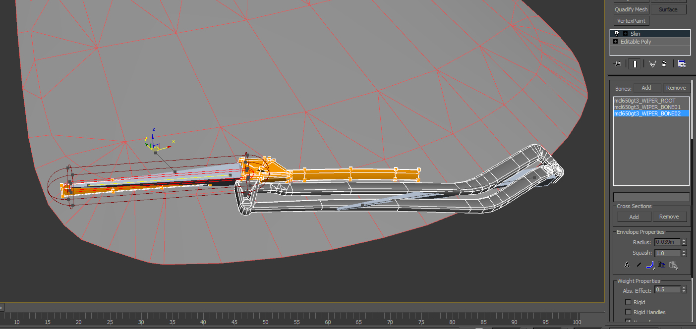
Image 19
Because you entered a value of 0.5, the vertices were only half-weighted to the blade bone. The remainder of the weighting is still assigned to the arm bone. Selecting bone 01 shows this more clearly:
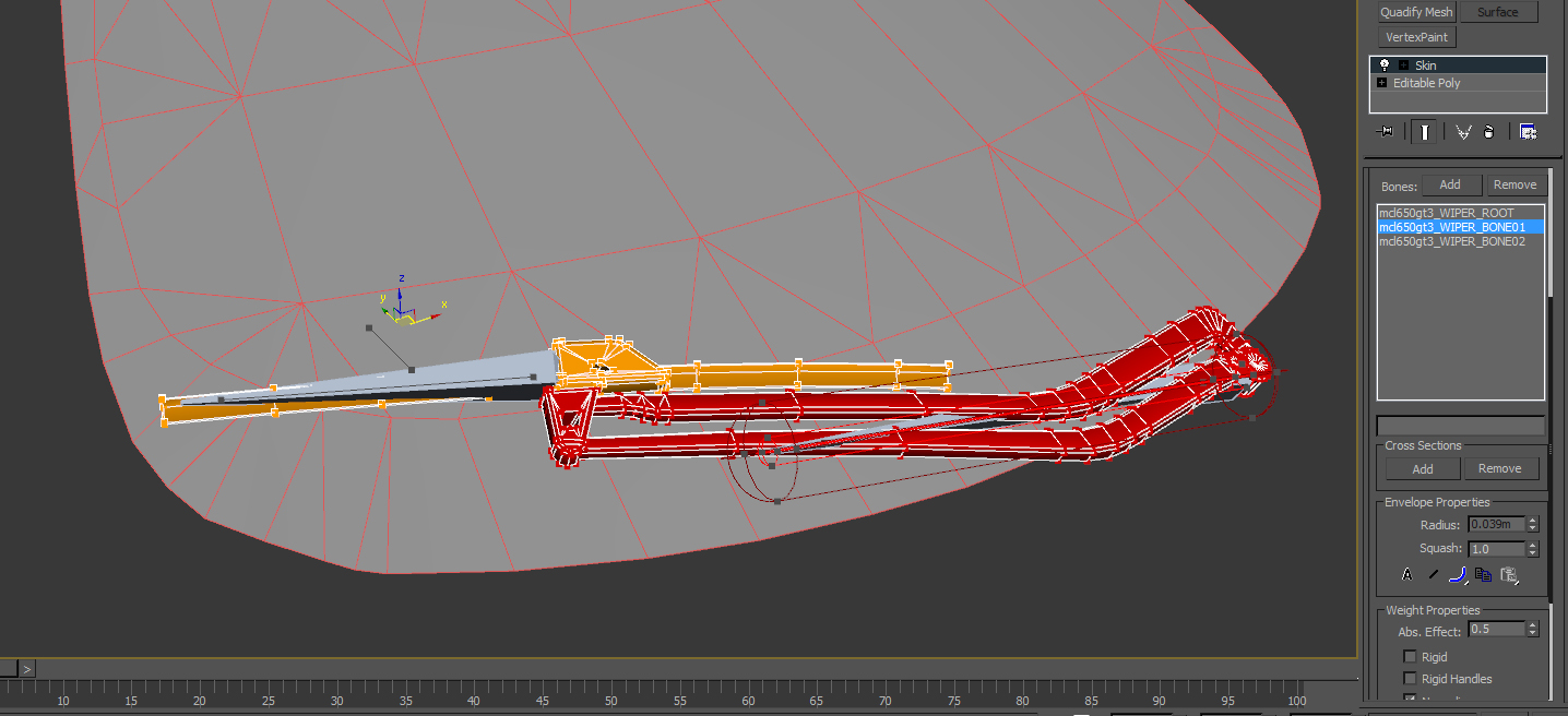
Image 20
You may find there are times where some vertices need to blend between two or more different bones (as is often the case with organic objects). For our wiper though, we can fully assign the blade to bone 02. So, making sure bone 02 is selected, enter 1.0 into the “Abs. Effect:” field. The blade will turn red, as you’d expected.
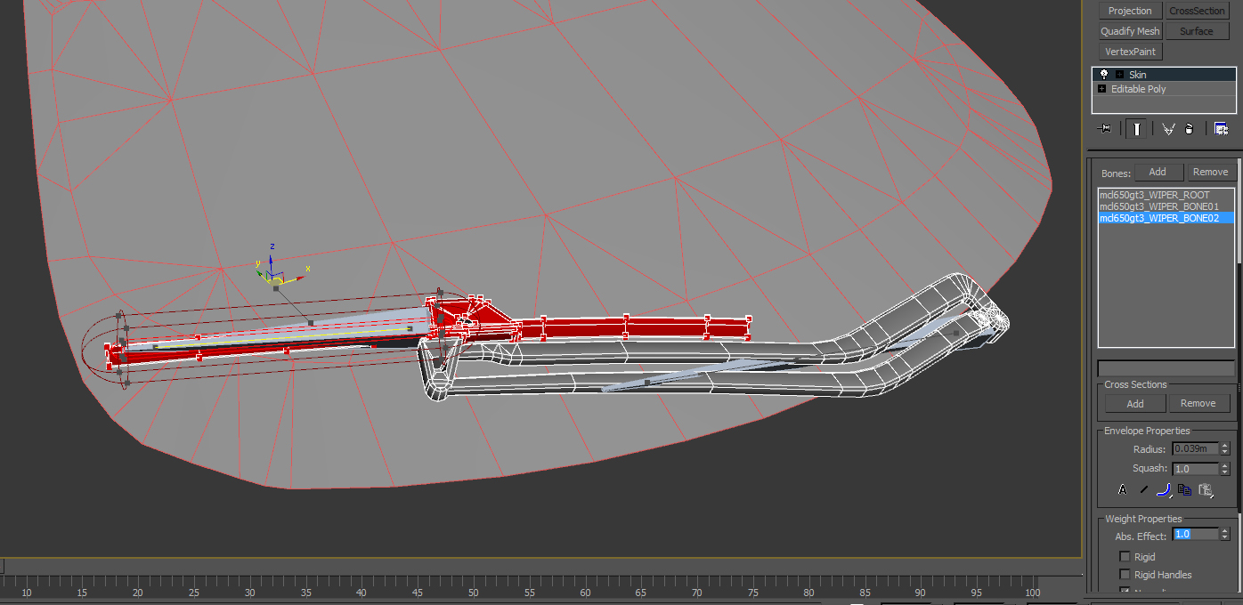
Image 21
Now for the “ROOT” bone. The need for a root bone becomes more obvious for objects that you need to move around the scene, such as a walking character, a root bone makes this much easier to do. For a static object it will simply ensure the object stays put. Thus, it’s “good form” for each rig to include a root bone, hence why I included it here.
If you think about it, all our vertices are now assigned to either bone 01 or bone 02. This means that NONE of them are assigned to the root. We don’t want this. Rather, each bone should have at LEAST one vertex assigned to it. If your wiper has geometry that will not move AT all, then you could assign these vertices to the root. If, however, your wiper object is like mine, this is not the case.
The easiest way to solve this without adding a bit of hidden “dummy” geometry is to slightly weight one vertex to the root. Obviously, it should be a vertex that will move very little. For my wiper, I will use one of the vertices at the base of the arm pivot, and that faces away from the cockpit camera so it won’t be noticed. To do this, select the root bone, and make sure “Select Element” is unchecked. Then select an appropriate vertex and enter an “Abs. Effect:” value of 0.01. When done, you should have something that resembles Image 22:
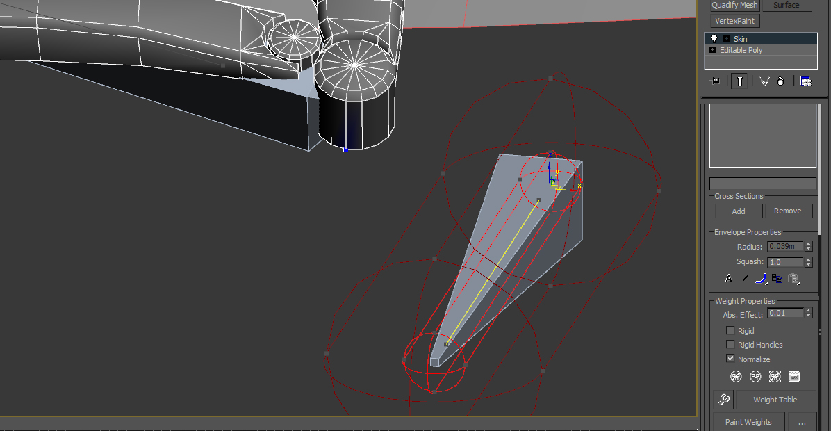
Image 22
Notice the blue vertex coloring: This indicates the slight weighting to the root. Since this vertex’s arm bone weighting is still FAR stronger, there should be very little distortion in its displacement. Disable “Edit Envelopes” in the Skin modifier to exit weight editing.
You can now test the vertex weighting (it’s also a good time to save your scene again so you can reload it after testing). NOTE: only rotate each bone once or twice, and then undo it. The bones MUST be in their “default” orientation when you start animating. Select a bone and rotate it. The vertices weighted to it should respond appropriately.
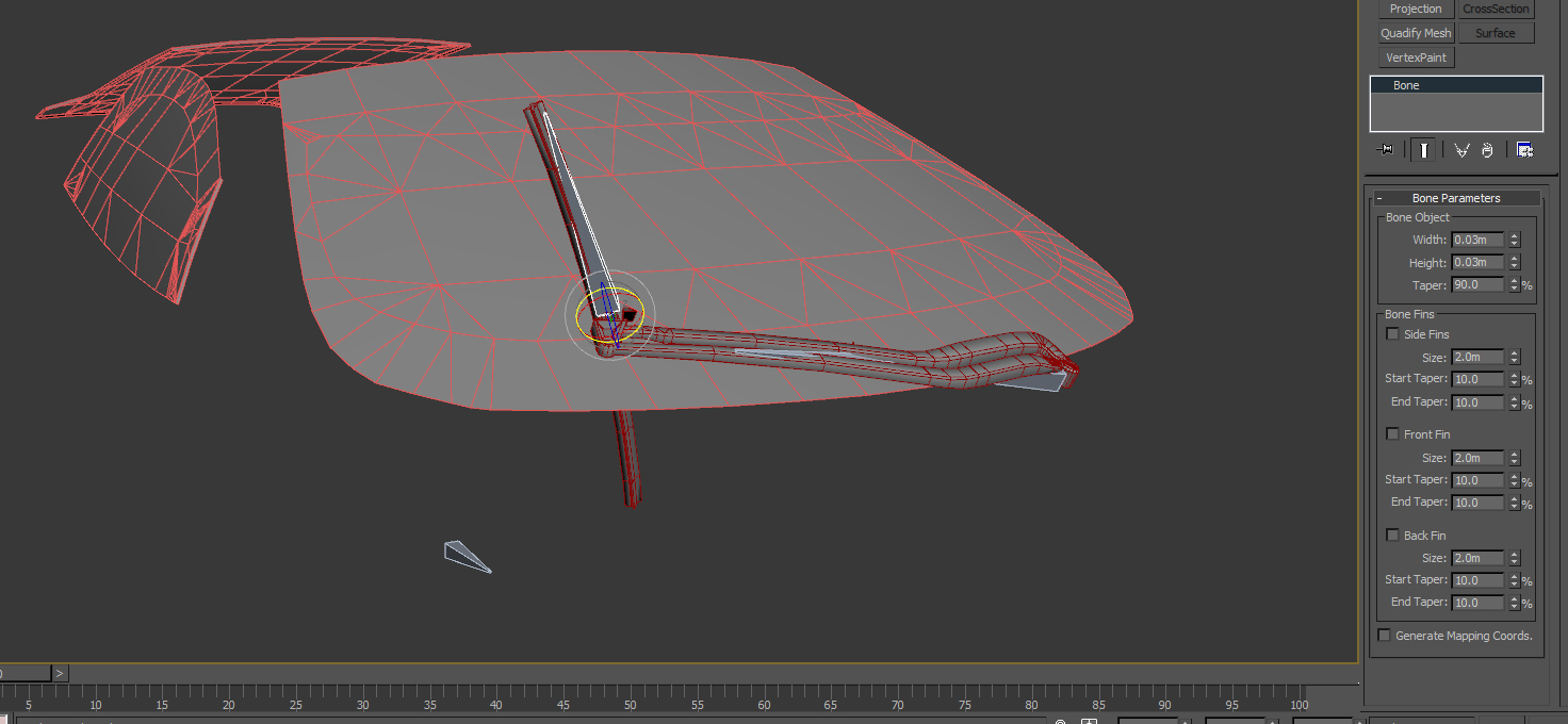
Image 23
In Image 23, I’ve rotated the blade bone. The blade portion of the wiper rotates with it. Image 24 demonstrates how the bone linking works: if I rotate the arm bone, the blade bone rotates with it.
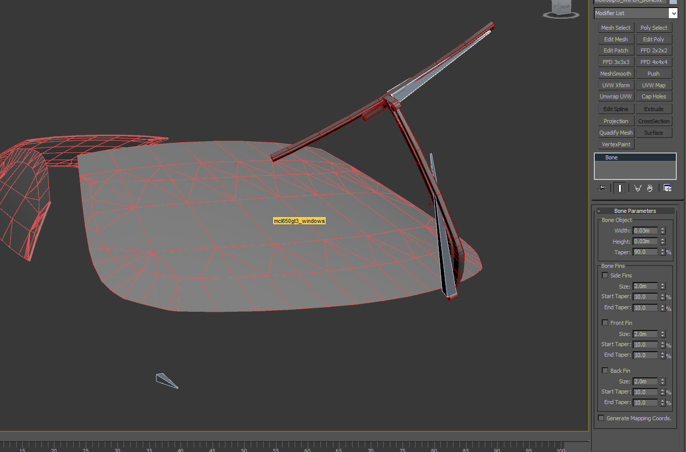
Image 24
If there is a vertex (or vertices) that doesn’t react as you expect, simply undo the bone rotation, select the wiper object, and edit the weighting for the vertex/bone in question. Since we did some very straight-forward weighting you shouldn’t have many issue to correct, if any. Once everything is the way you want it, you’re ready to begin animating.
Animating
I would suggest taking a traditional animator’s approach to animating in 3D--setting up a series of primary poses throughout the length of the animation, or (“Keyframes”). By doing this, you can quickly work out timing, motion and expression. This is especially true for animated characters and other organic objects. Mechanical objects are much easier to animate; but again, the keyframes will help you quickly lay out the overall timing and motion of the object.
Once the keyframes are set, you will then fill in with more and more detailed frames (“Inbetweens”). This process allows you to add fluidity, weight, definition and subtlety to your animation. Inbetweening in 3D is easier because the software will do its best to fill in the motion between the keyframes for you. You certainly WON’T have to pose each and every frame. However, the more keys you provide the software, the closer to your intended motion the animation will be. So, let’s begin by setting up the keyframes for our wiper animation.
As with everything, a bit of setup will make you life easier when animating. First, let’s reduce the number of frames to only what we’ll need. Animations in rFactor 2 can be any length, but to be efficient you want the shortest possible. In the case of our wiper, we use an animation length of 21 frames (from frame 0 to frame 20). However, I find that this is too few frames for proper keyframing, so we’re going to set the animation longer than we need for now.
If you right-click on the animation “Play” button you will open the “Time Configuration” window (Image 25). Do this; and then, in the “Animation” field, set the “End Time:” to 48, and click “OK”. You will see the time bar length change from 0-100 to 0-48.
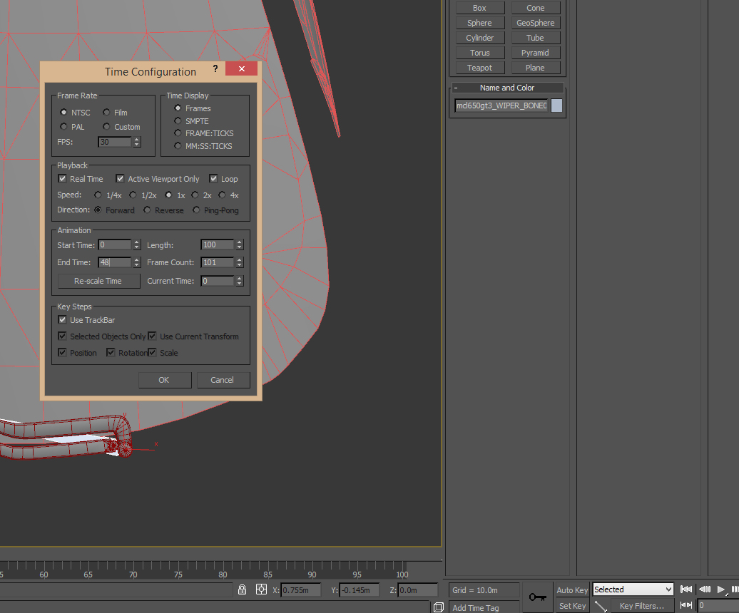
Image 25
You can also define how the software will “fill in” the frames between the keys that you set. For MOST animations, you’ll either want to use “Linear” or “Smooth”. For mechanical animations Linear normally is what you’ll want to use, but Smooth is a viable option if you want a more gradual motion from one key to the next. To set a default style for each new key you create, use the “Default In/Out Tangent For New Keys” button. Press and hold to show a list of different tangent types, and select either Smooth or Linear (Image 26)
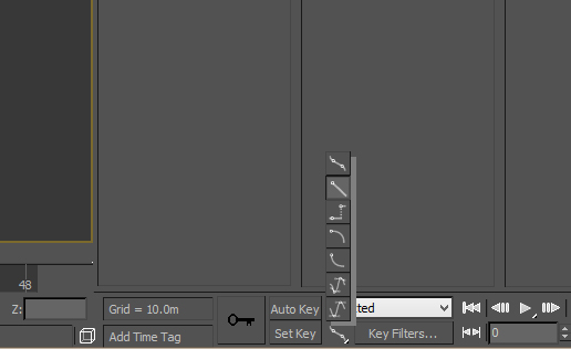
Image 26
All bones need at least ONE keyframe, and this should be at frame 0 in order to hold our initial position. (NOTE: while we won’t need this for the wiper, many objects, such as characters, will have a “T-Pose” that needs to be keyed at frame 0 but is not actually part of the animation. At export, you would use the “Skip Frame 0” option in the “Get Frames From:” section of the gMotor exporter). The easiest way to do this is to select all the bones for your object, right-click on the Time slider at frame 0, and open the “Create Key” window (Image 27).
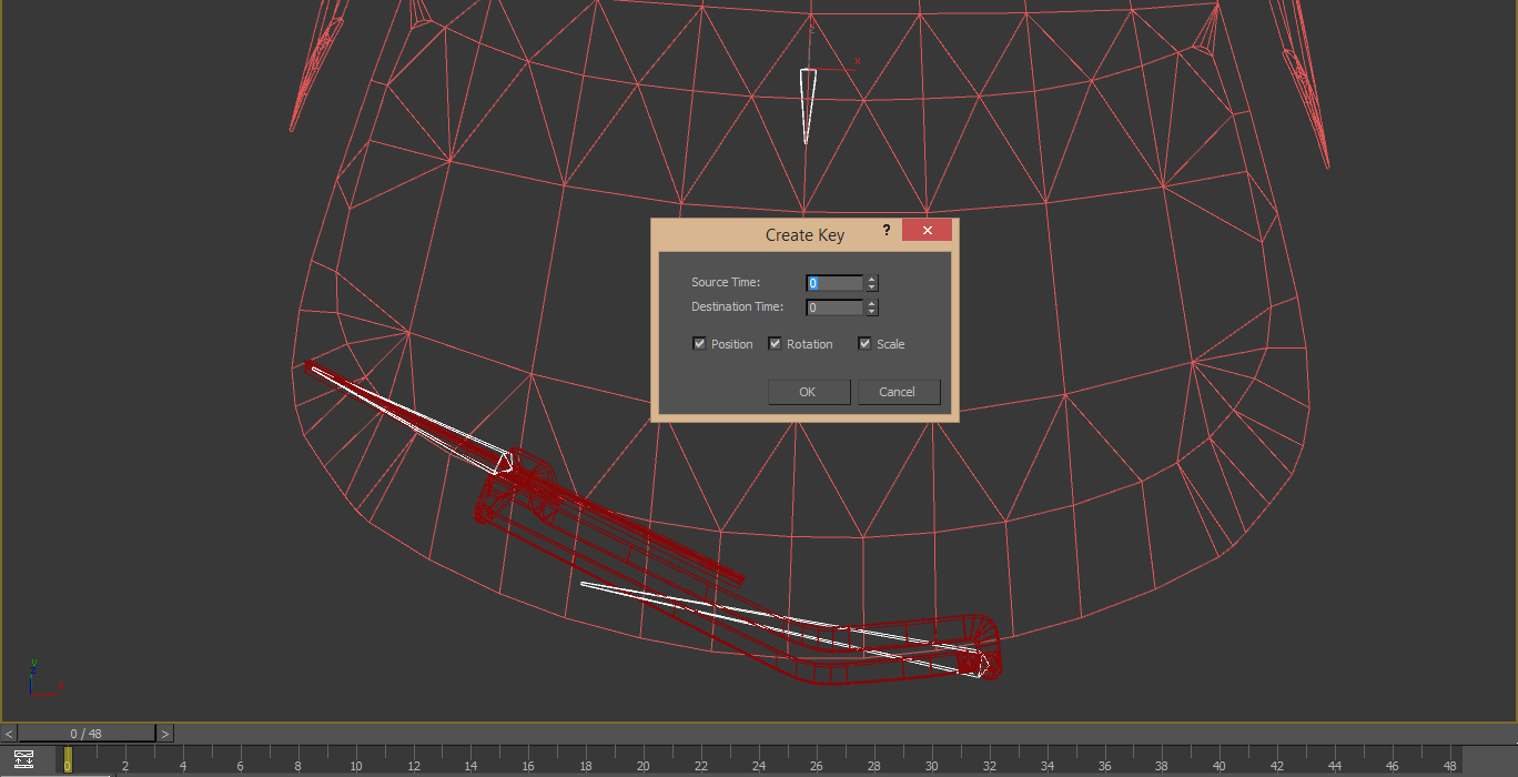
Image 27
As you can see, there are check boxes to only set specific types of keys, and you can also set a key based on the bones’ attributes from one frame (Source Time) to another (Destination Time). For this, we just need to click “OK” using the basic settings as shown in Image 26. Since the root bone will be static throughout the animation, you can set another key for it on the last frame. To do this, select the root bone and either:
Select the key at frame 0 and shift-drag it to the last frame, thus making a copy.
Slide (also known as “scrubbing”) the Time slider to the last frame, right-click, and again use the Create Key window.
Let’s define the keys for the wiper arm bone. It will sweep from its initial position at frame 0, to the other side of the windshield halfway through the animation (frame 24 based on our time bar), and finally back to initial position at the final frame (frame 48). Scrub the Time Slider to frame 24. Also, be sure to click on the “Auto Key” to enable it. A red border will appear around the workspace window, as shown in Image 28.
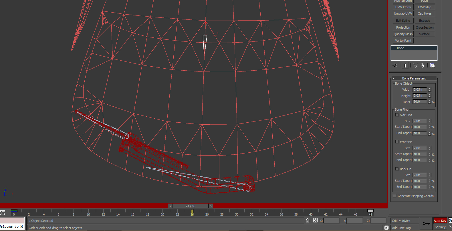
Image 28
With Auto Key enabled, any change in an object’s scale, position or rotation will be recorded as a keyframe (or update the current keyframe if there is already one on the given frame). Now, select the wiper arm bone; and, again using its “Local” Reference Coordinate System, rotate the bone so the wiper rotates to the other side of the windshield (Image 29).
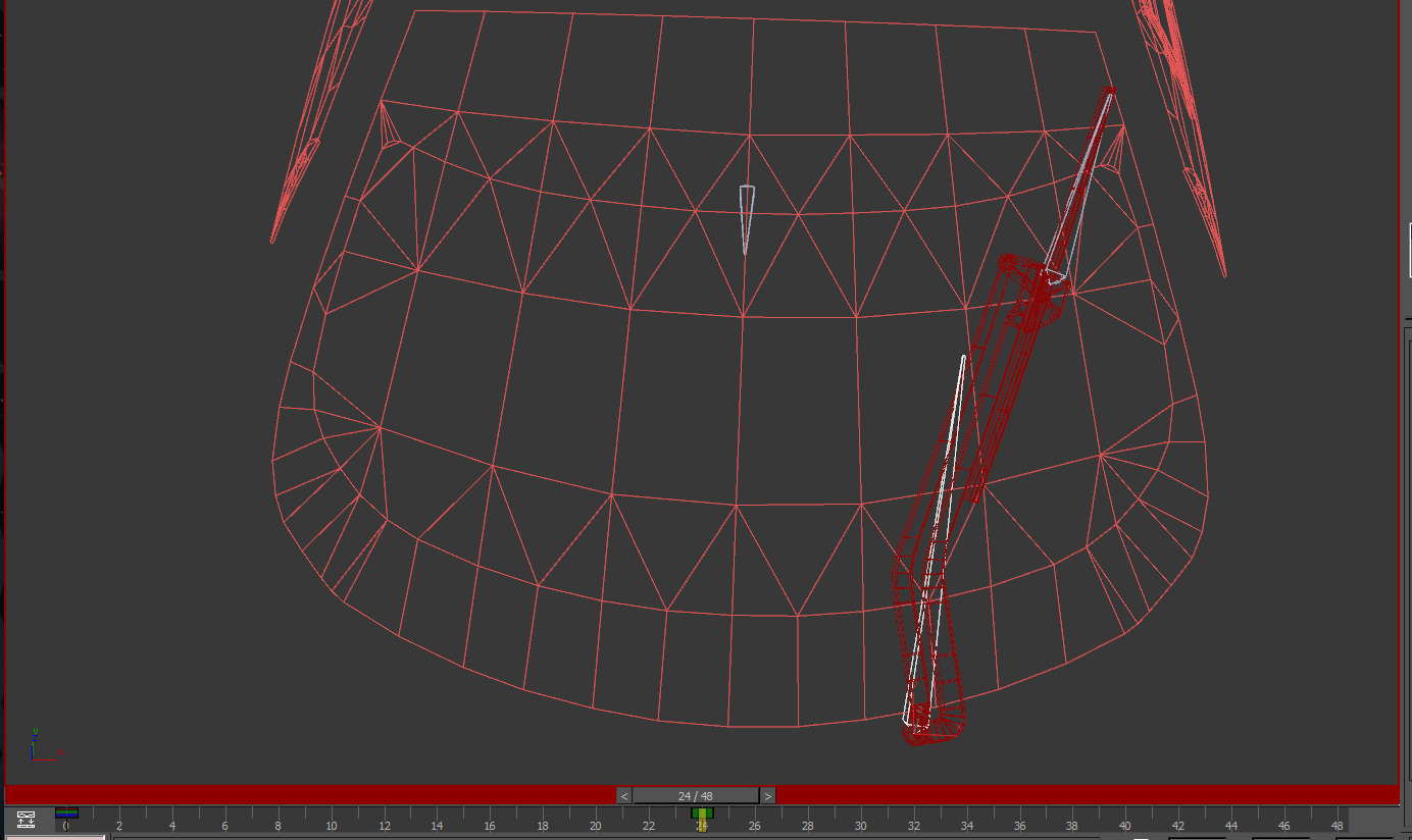
Image 29
As you rotate the wiper arm along one axis (probably the Y) for the sweep, if you look at a side view you’ll notice that it may have penetrated the windshield. Still on frame 24, rotate the arm so that it is above the windshield (Image 30).
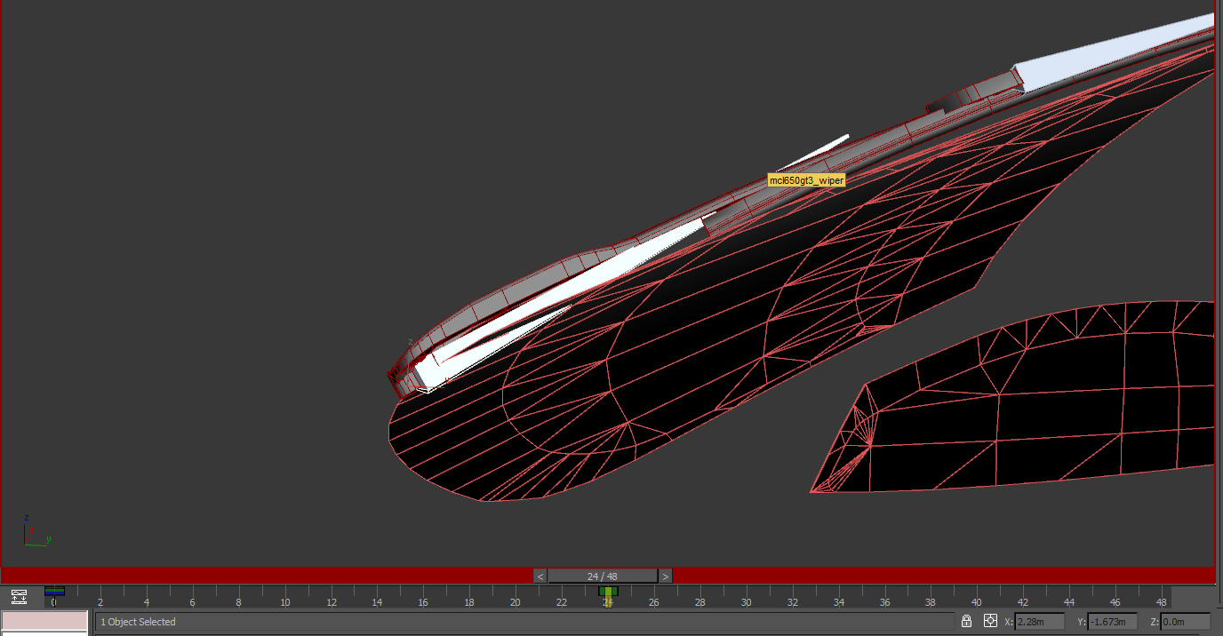
Image 30
As the arm sweeps across the windshield screen the blade will need to pivot so that it stays level with the windshield. Let’s set a key, on the same frame, for the wiper blade bone. With the blade bone selected, rotate the view around it to find a good angle, and rotate the bone into place, as I’ve done in Image 31. (NOTE: you may have to switch back and forth between the arm and blade, tweaking the rotation of both, to get everything into place)
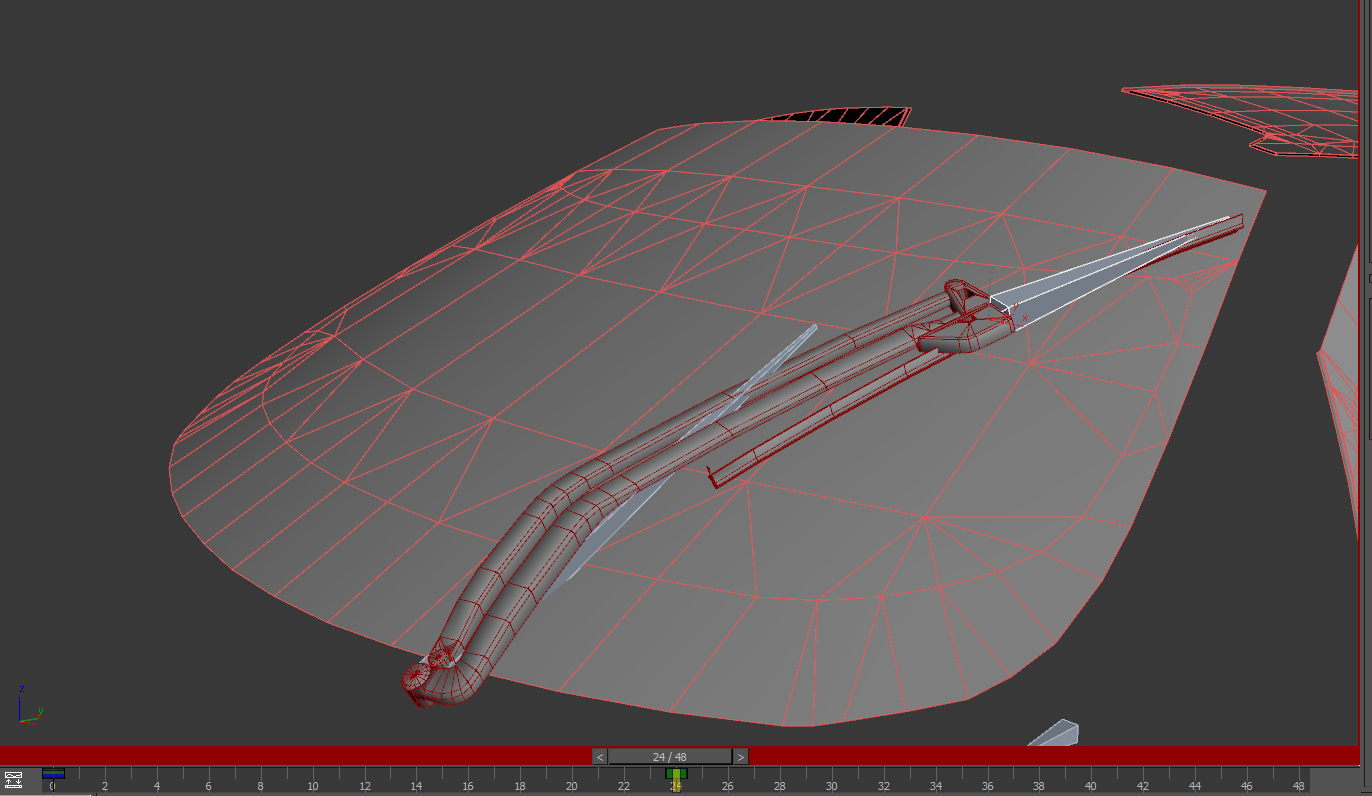
Image 31
Remember, you want the blade aligned with the windshield, and as close as possible, without penetrating it (Image 32), or any other object that rests on the windshield, such as a glare stripe. Again, don't get frustrated if you find you have to switch back and forth between arm and blade bones.
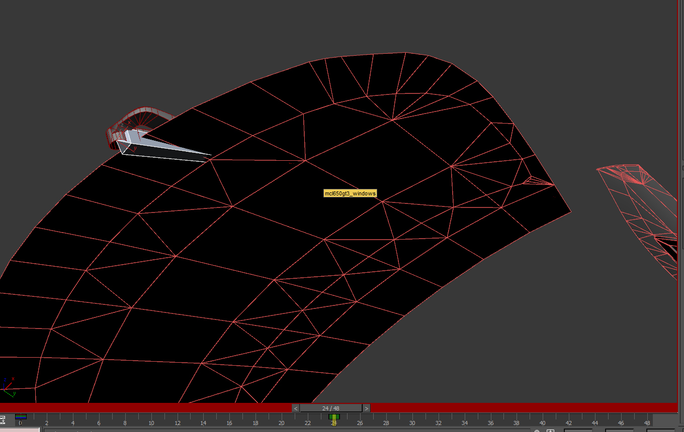
Image 32
Now, let’s set keyframes for the arm and blade bone at the end of the animation. Again, we want the wiper to end in the same position it started in. So, for each bone, select the key at frame 0, and shift-drag it to frame 48 (Image 33). Don’t worry, you won’t mess up the key at frame 24 unless you release the copy on to it.
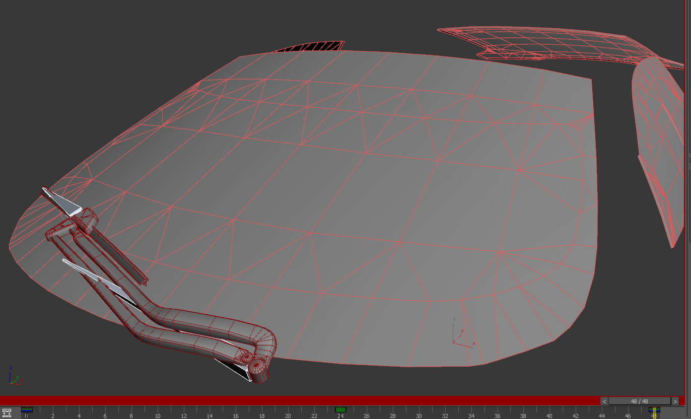
Image 33
If you scrub the Time Slider back and forth, you should see the wiper sweep across the windshield and back again. It will most likely clip through the windshield as it does. We’re going to fix that with Inbetweens. Let’s think of each section of animation time, between each keyframe, as a segment. I like to continuously divide each segment in half with more and more inbetweens until the animation is finished. With this in mind, scrub the Time Slider to frame 12, and rotate the arm and blade bones to move the wiper into the proper position. Then do the same at frame 36. I’ve done this in Image 34:
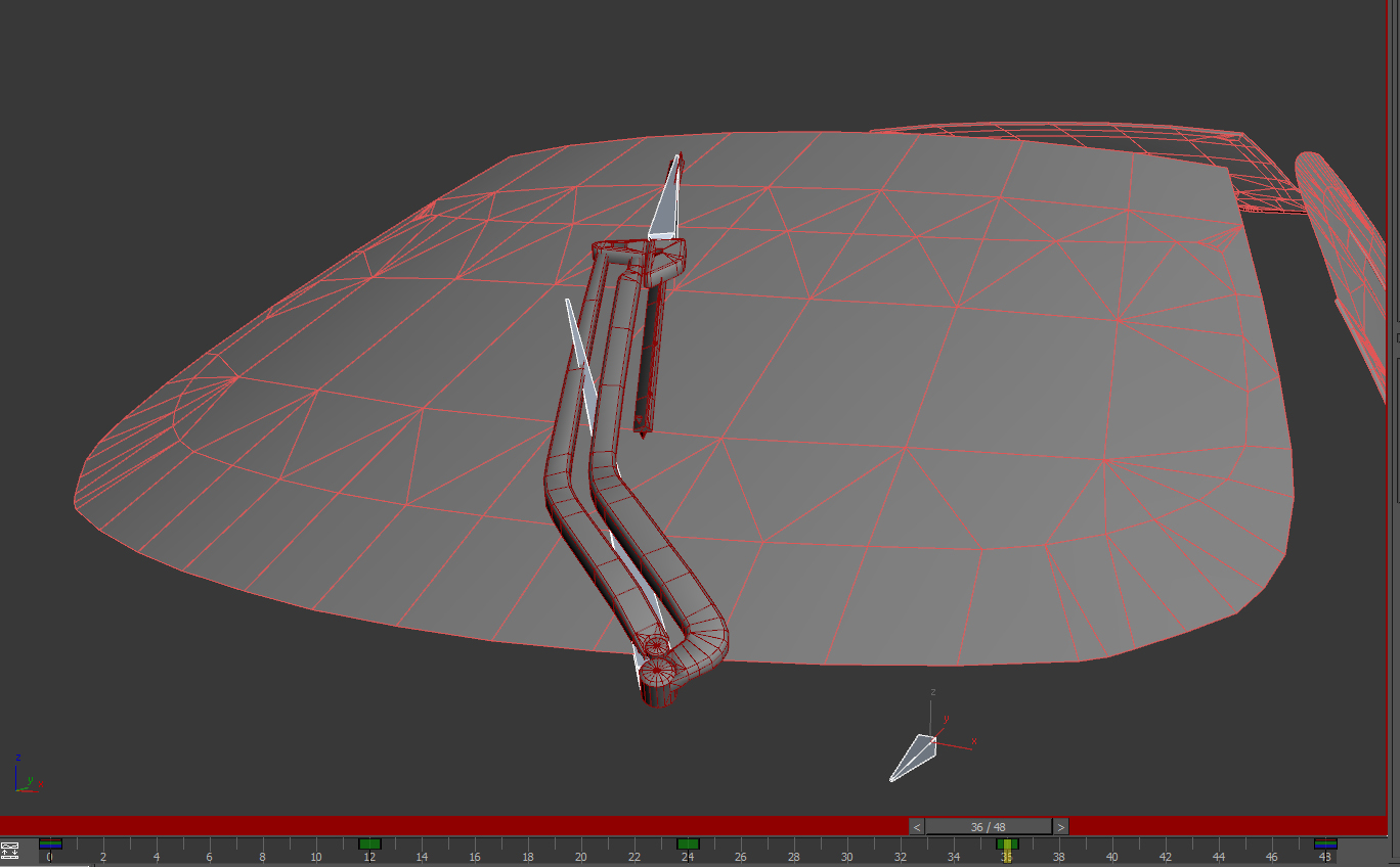
Image 34
Now, when you scrub the Time Slider back and forth, the wiper should track with the windshield MUCH better. Continue to refine the animation by adding more and more inbetweens until the wiper tracks smoothly across the windshield while NEVER letting the blade clip through it. (NOTE: Save OFTEN, either manually or with auto-save, so if you make a mistake, or MAX crashes, you don’t lose a lot of work). When you’re done, be sure to disable “Auto Key”. Your animation should look very similar to Image 35:
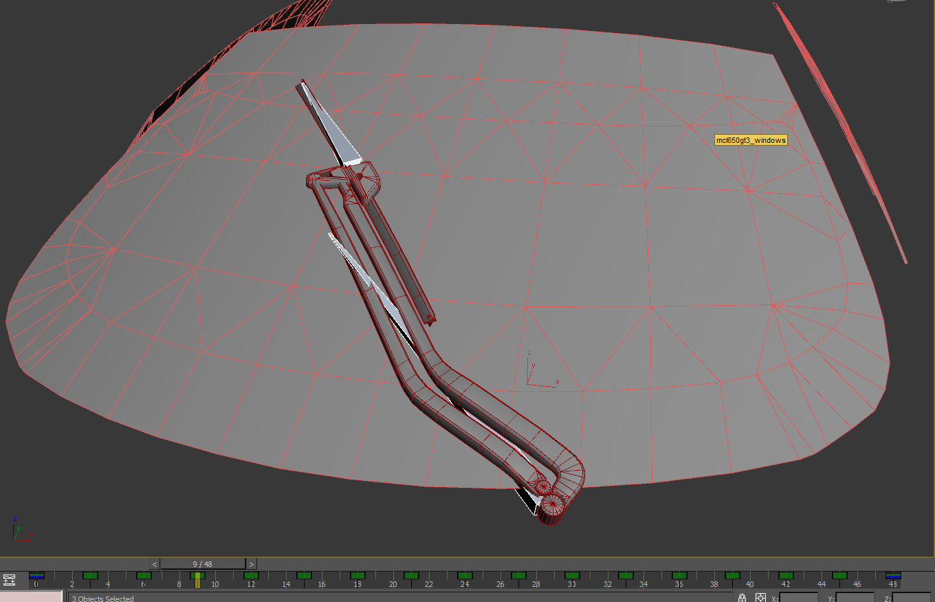
Image 35
Since this is a rather quick-moving object, you may notice a bit of a “micro-pause” when the animation loops. This is because the first and last frames are exactly the same. The easiest way to deal with this (especially when using Linear keys) is to create a keyframe at the second-to-last frame, and then set the animation to loop on THAT frame. This will effectively remove the duplicate frame, thus creating a smoother loop. To do this, select all the bones, scrub the slider to the second-to-last frame (frame 47 for my wiper animation) and then right-click the Time Slider to open the Create Key window. Make sure the Source and Destination frames are both correct, and create a key. I’ve done this in image 36:
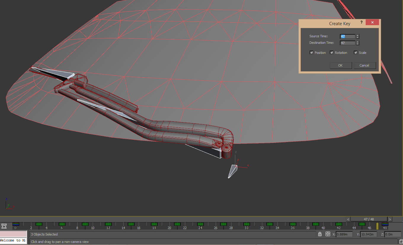
Image 36
(NOTE: Conversely, to create an even smoother loop, you can open the Curve Editor and tweak the In/Out tangents of the first and last keys. The Curve Editor is a whole other beast on its own, and is beyond the scope of this tutorial. Though, if you’re serious about animating, you will DEFINITELY want to learn how to use it!)
When the key is created, open the Time Configuration window (again, by right-clicking on the animation “Play” button), and set the new “End Time:” to be the current second-to-last frame (again, frame 47 in my example). The micro-pause when the animation loops is now dealt with.
(WARNING: Before the next step, I STRONGLY recommend making a backup of the “finished” animation, in case you have to go back and make revisions to it later!)
For wiper animations, we want the length to be 21 frames, from frame 0 to 20. Obviously, we’ll need to rescale it. To do this, again right-click on the animation Play button and open the Time Configuration window. Click on the “Re-scale Time” button. In the “Re-scale Time” window, set the end time to 20 and click “OK” (Image 37).
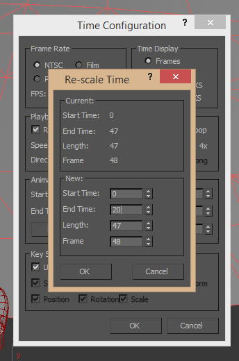
Image 37
When you do, the animation length will be rescaled. Notice that some of your keys are “offset” from the frame numbers. This is because the keys are based on time, and their new scaled time falls between two frames. This is why you want to save a backup of the animation in its unscaled state--working with “offset” keys is not easy. Of course, you could also animate from the start using the 21 frame length, if you prefer. Animation is a rather “personal-preference” sort of skill.
Exporting
With the animation finished, it’s time to export it. Unlike typical objects in rFactor 2, for animated objects you not only need to export the object itself, but also an animation file (.ANM). This is pretty easy to do; however, for some gameplay-related objects, such as the wiper, there are some naming conventions to adhere to. Open the GMT Converter from the Utilities tab and I’ll go over the wiper setup (other objects are VERY similar).
Let’s discuss naming first, especially since it is critical for the wiper. In the “Animation” panel of the GMT exporter, you’ll first want to select a folder to export the .ANM file to. Do this using the first text/browser field (which currently is mislabeled as “Animation”). In the second line, enter a name for the animation file. For wipers, this needs to be CarCame_wiper.ANM. Finally, we want to name the animation itself. This MUST be WIPER.ANM
To export an animation, you need to have the object selected AND all the bones used for the animation. In the “Anim Type:” section, make sure “Selected Nodes” is set. The “Root Node:” is whatever object or bone is used as the root. You can use the object selector to grab this from the list.
In the “Get Frames From:” section, we want to use “Keyframes”. The “Start:” and “Stop Frame:” should be the initial frame (frame 0 for my example), and the frame of the last key of the animation (frame 20 for the wiper). Since our wiper does not have a “T-Pose” we don’t have to “Skip Frame 0”, so make sure that is unchecked. Once this is all set (and again, be sure not only the object but also ALL the bones used in the animation are selected), click “Do Anim”.
When the exporter is finished creating the animation, you’ll get a small “Conversion Successful” window, if all went well; and, your new .ANM file will be created in the folder you specified. Image 38, below, shows the Animation panel with proper settings, and the successful conversion:
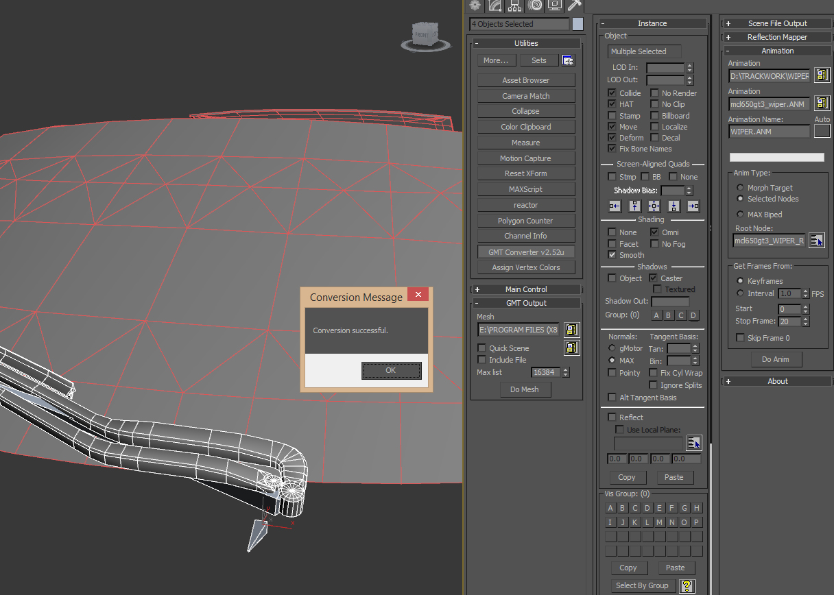
Image 38
To export the object itself, you are free to use whatever settings you deem necessary; however, you should be sure “Move”, “Deform” and “Fix Bone Names” are all checked. These are located in the exporter’s “Object” panel.
Conclusion
It seems a lot to take in; and honestly, it is. Animation is NOT easy; and not everyone can do it (especially where character animation is concerned). Professional animators spend their entire careers perfecting their skill in just this one area. However, with some practice, it’s easy to pick up the basics; and they are easily applied to the types of mechanical animations you’d expect to encounter for things such as wipers in rFactor 2. With that, I do hope this general animation tutorial, with a focus on windshield wipers, will help get you started with a solid footing.